Insert Molding | Process, Considerations, and Applications
This article explains insert molding for plastic injection molded parts with metal, plastic, or electronic inserts. The practical RFQ problem is deciding whether insert molding can reduce assembly work while still controlling insert position, plastic flow, pull-out strength, insulation, corrosion risk, shrinkage, flash, and dimensional inspection.
How Insert Molding Combines Inserts With Injection Molded Plastic
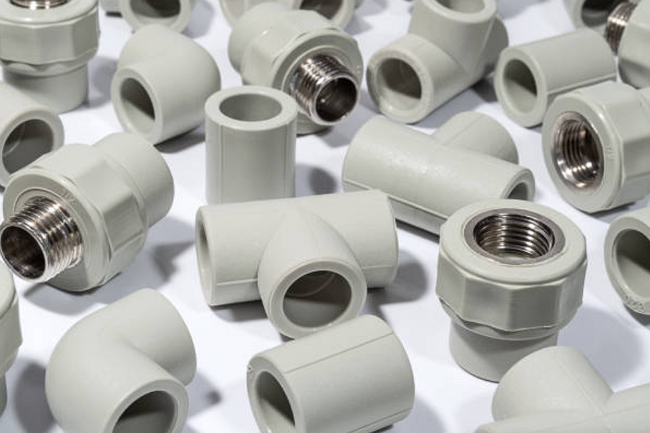
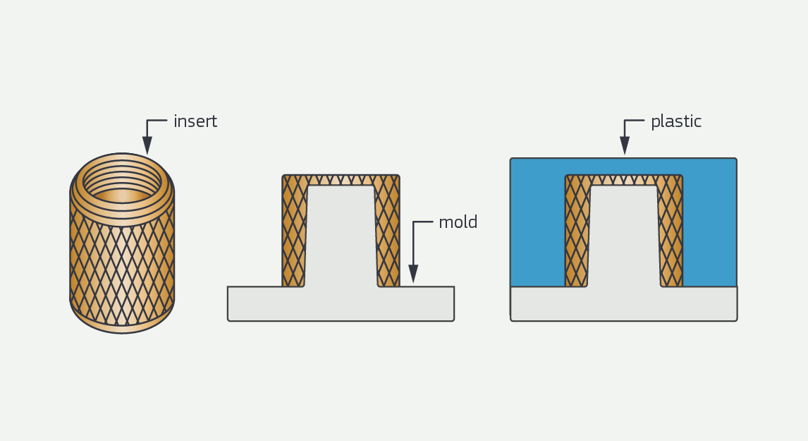
Insert molding places a prepared insert into an injection mold before molten plastic fills the cavity. The insert may be a threaded bushing, pin, contact, magnet, shaft, stamped metal part, machined component, or molded plastic part. The injected plastic locks around the insert and forms an integrated part after cooling.
Insert molding can reduce screws, adhesives, and secondary assembly, but the insert must stay in position during mold closing and injection. Buyers should define insert material, insert tolerance, plastic resin, pull-out load, torque requirement, insulation requirement, cosmetic faces, and inspection criteria before tooling review.
Buyer Question | Insert Molding Answer | Manufacturing Reason | RFQ Detail Needed |
|---|---|---|---|
Why use insert molding? | To combine a pre-made insert with a molded plastic body | The plastic can mechanically retain or encapsulate the insert | Insert drawing, plastic resin, pull or torque requirement |
What controls insert position? | Fixture design, insert tolerance, mold locator, and injection pressure | Plastic flow can move unsupported inserts | Insert datum, orientation, acceptable movement |
What can fail? | Insert shift, short shot, flash, sink, cracking, or weak pull-out | Metal and plastic respond differently to heat and pressure | Critical dimensions, test method, acceptance criteria |
Insert Preparation, Placement, Molding, Cooling, and Ejection Steps
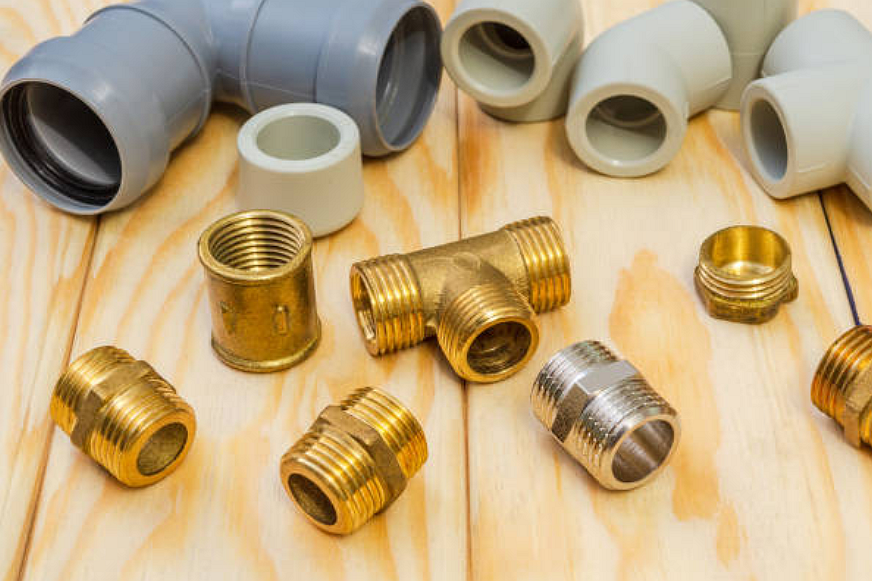
The process starts with insert preparation. Inserts may need cleaning, drying, plating review, knurling, grooves, holes, undercuts, or surface texture. Insert condition affects plastic bonding, mechanical retention, corrosion risk, and electrical contact where conductive inserts are used.
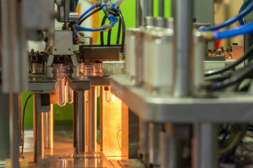
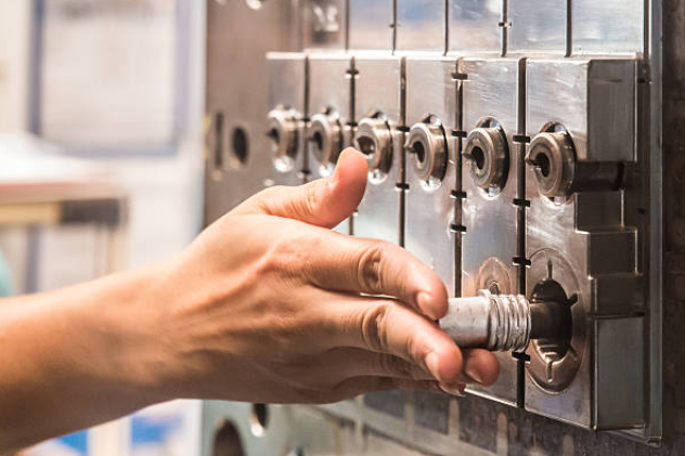
The insert is placed into the mold by hand, fixture, robot, or automated loading system. After the mold closes, molten resin flows around the insert. The tool must support the insert so the injection pressure does not move it. After cooling, the part is ejected and inspected for position, flash, cracks, short shot, sink, and insert retention.
Insert Molding Stage | What Happens | Risk to Control | Buyer Confirmation Needed |
|---|---|---|---|
Insert preparation | Metal or plastic inserts are cleaned, checked, and oriented | Contamination, burrs, plating damage, wrong orientation | Insert drawing, surface condition, incoming inspection |
Insert placement | Insert is located inside the mold cavity | Insert shift, mold damage, cycle variation | Locator design, insert tolerance, automation need |
Plastic injection | Resin flows around the insert and fills the cavity | Short shot, flash, voids, weld line, stress concentration | Resin grade, gate location, cosmetic faces |
Cooling and ejection | Part solidifies and leaves the mold | Cracking, warpage, insert loosening, ejector marks | Critical dimensions, packaging, retention test |
Insert Molding Materials, Inserts, Resins, and Retention Features
Insert molding material selection should consider insert metal, plating, resin shrinkage, thermal expansion, corrosion exposure, electrical insulation, and mechanical load. Common insert materials include brass, stainless steel, carbon steel, aluminum, copper alloy, magnets, pins, and stamped contacts. Common resin choices may include ABS, nylon PA, PP, POM, and PEEK, subject to design and use environment.
Material Entity | Role in Insert Molding | Manufacturing Risk | RFQ Detail to Define |
|---|---|---|---|
Threaded metal insert | Provides thread strength or repeated fastening | Insert shift, pull-out, torque failure, plastic cracking | Thread size, torque, pull-out load, plating condition |
Stamped contact or pin | Provides electrical or mechanical interface | Short shot, insulation gap, alignment issue | Contact position, conductivity need, insulation requirement |
ABS, PA, PP, POM, or PEEK resin | Forms the molded body around the insert | Shrinkage, stress, heat deformation, moisture sensitivity | Resin grade, filler content, operating environment |
Insert Shift, Pull-Out, Cracking, Flash, and Inspection Risks
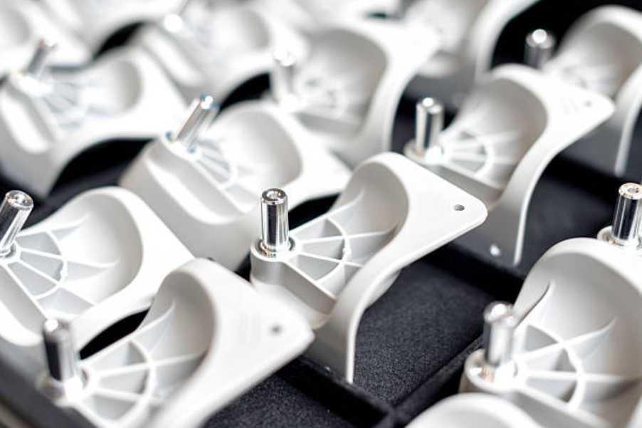
The main insert molding risks are insert movement, insert tilt, plastic cracking, voids around the insert, weak pull-out strength, poor torque resistance, flash, sink marks, and short shots. These issues are often connected to insert tolerance, fixture support, gate location, plastic shrinkage, and mold shutoff strength.
Part Feature | Insert Molding Risk | Design Review Focus | Inspection Evidence |
|---|---|---|---|
Threaded bushing | Pull-out failure, torque failure, cracked boss | Knurl, undercut, boss thickness, resin selection | Torque test, pull-out test, dimensional report |
Electrical contact | Misalignment, insulation gap, short shot | Locator design, shutoff, resin flow path | Continuity check, visual inspection, position check |
Metal insert near cosmetic surface | Sink mark, read-through, flash | Wall thickness, gate location, cooling | Visual standard, dimensional report |
Large insert in small plastic body | Stress, warpage, weak retention | Insert mass, resin shrinkage, support ribs | CMM report, fixture check, sample approval |
Insert Molding vs Overmolding and Traditional Injection Molding
Insert molding places a pre-made insert into the mold before plastic is injected. Overmolding molds a second material over a substrate to add grip, sealing, cushioning, or protection. Traditional plastic injection molding produces a molded plastic part without a pre-loaded insert unless the insert is added later by assembly.
Process Route | Typical Use | Manufacturing Constraint | Buyer Decision Point |
|---|---|---|---|
Insert molding | Threads, pins, contacts, bushings, magnets, structural inserts | Insert placement and retention must be controlled | Insert tolerance, pull-out load, automation need |
Overmolding | Soft grip, seal, cushion, color band, protective layer | Material compatibility and two-shot molding conditions matter | Adhesion, hardness, substrate material |
Traditional injection molding | Single-material housings, covers, clips, brackets | Secondary assembly may be required for metal features | Assembly cost, resin grade, part geometry |
RFQ Inputs and Inspection Evidence for Insert Molded Parts
An insert molding RFQ should include 3D CAD, 2D drawing, insert drawing, resin grade, insert material, insert surface finish or plating, expected quantity, annual volume, critical dimensions, pull-out or torque requirement, electrical or sealing requirement, visible faces, and inspection criteria.
Useful inspection evidence may include incoming insert inspection, dimensional report, FAI, CMM report, go/no-go gauge, torque test, pull-out test, continuity check, leak test, visual standard, material certificate, and sample approval. If the molded part is used in a regulated or safety-critical assembly, final validation remains the buyer's responsibility.
RFQ Input | Why It Matters in Insert Molding | Quotation Impact | Possible Inspection Evidence |
|---|---|---|---|
Insert drawing and tolerance | Controls mold locator, insert fit, and part position | Affects fixture design, automation, and scrap risk | Incoming inspection, CMM report, go/no-go gauge |
Resin grade and filler content | Controls shrinkage, strength, heat behavior, and flow | Affects mold design, cycle assumptions, and validation | Material certificate, dimensional report |
Pull-out, torque, or electrical requirement | Defines functional acceptance beyond appearance | Adds testing, retention feature review, and sampling plan | Pull-out test, torque test, continuity check |
Production stage | Prototype, pilot, and production runs require different controls | Affects sample approval, fixture development, and inspection plan | FAI, pilot lot report, production inspection record |
Related FAQs
What Is the Difference Between Insert Molding and Overmolding?
What is insert molding, and how does it differ from traditional molding processes?
Are there limitations or challenges associated with insert molding?
What are the main challenges when implementing insert molding?
What are the common challenges in insert molding, and how can they be resolved?