What is An Example of Insert Molding?
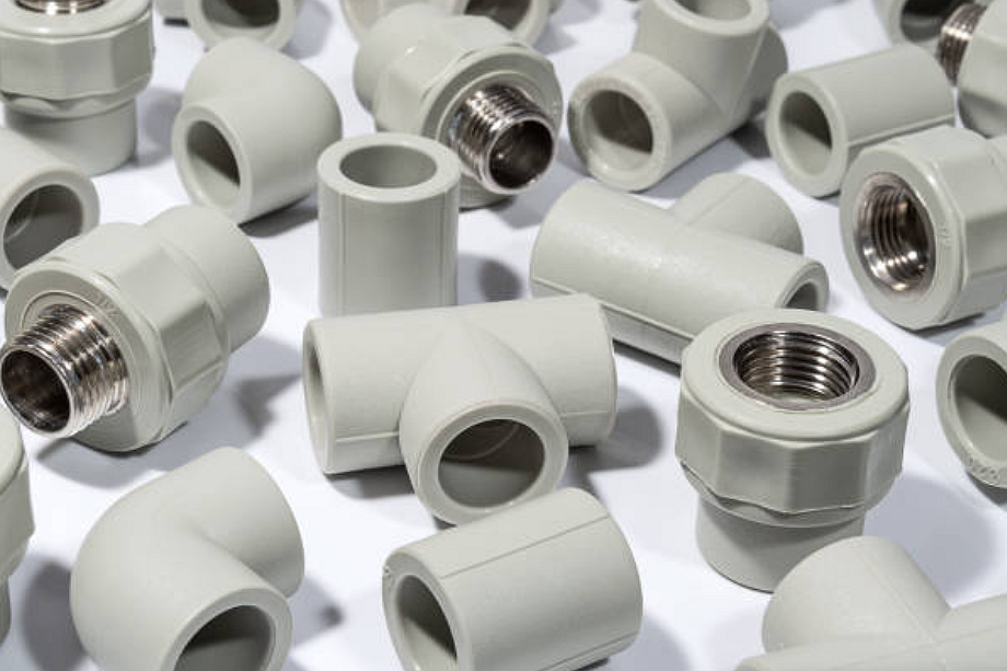
Insert molding refers to an injection molding process where a pre-fabricated component or insert is placed into a mold cavity and encapsulated within molded plastic. One typical example of insert molding is manufacturing electrical connectors encapsulated in plastic housings.
Electrical Connector Insert Molding
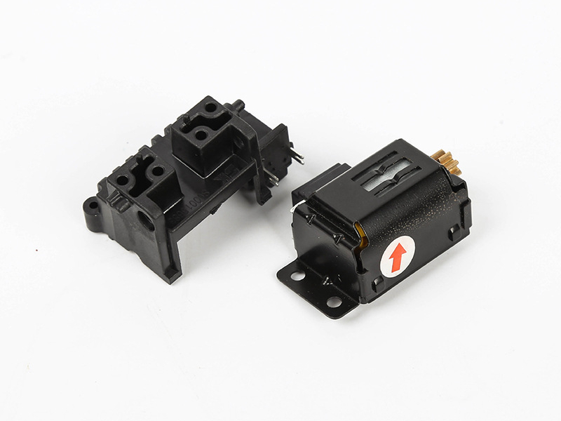
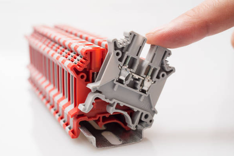
Insert molding regularly produces electrical connectors and terminal blocks encased within molded plastic bodies. It provides protection, insulation, and structure to the metal contacts and wiring.
Connectors may be simple pin and socket types or complex multi-pin arrays used in various industries. Applications range from automotive wiring harnesses to connectors in consumer electronics, telecom equipment, and industrial control systems.
Benefits of Using Insert Molding
There are several benefits to encapsulating metal electrical contacts within molded plastic housings versus post-assembly:
- Creates a unified one-piece component
- Provides electrical insulation and isolation
- Allows molded-in strain reliefs and clip features
- Offers flexibility for connector positioning and orientation
- Enables high-volume production efficiency
- Eliminates secondary assembly steps
- Reduces total part and system costs
Molded features like flanges, thread bosses, alignment pins, clips, and cable strain reliefs can be incorporated for installation and reliability. Plastic insertion also provides complete encapsulation and environmental sealing.
Insert Molding Process Steps
Producing insert molded electrical connectors involves the following steps:
1. The metal terminals and wires are pre-fabricated based on connector design requirements. It may involve stamping, bending, crimping, and pre-wiring pins and sockets.
2. The contact inserts are optionally tested for electrical continuity and insertion force before molding. It verifies component quality before encapsulation.
3. Inserts are loaded into designated cavities within a multi-cavity injection mold manually or by automation. Precise positioning and orientation are critical.
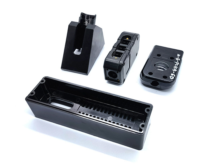
4. The mold closes, and the molten thermoplastic resin is injected under pressure to fill the cavities. Common plastics are PBT, nylon, ABS, polycarbonate, or PPS.
5. Plastic flows around the inserts, encapsulating them entirely within the housing while leaving contact areas exposed.
6. Pins and molded features are precisely formed by core and cavity details—the plastic bonds to the insert.
7. After cooling, the mold opens, and the finished connector components are ejected.
8. Parts are then trimmed, stamped, or engraved as needed before final testing and shipment.
There are two main insert molding techniques used for electrical connectors:
- Hot tip insertion molding
- Two-shot molding
Hot Tip Insertion Molding
The pre-wired connector inserts are heated with this method until the terminal tips are molten. The inserts are then placed into mold cavities where plastic fully encapsulates the body while fusing with the melted tips. It creates a solid consolidated component after re-solidifying the mold.
Two-Shot Insert Molding
Two-shot, or multi-shot molding, refers to injecting a secondary resin specifically onto the insert contact areas to achieve bonding. The first shot encapsulates the body, while the second shot bonds to the tips. It provides adhesion without heating the inserts.
Multi-shot techniques are also used to create connectors with two-tone aesthetic effects by molding the body and face in different colored resins.
Design Considerations
Effective insert molded connector design requires considering the following:
- Insert geometry to match resin flow and molding dynamics
- Overlap required for sufficient bond strength
- Undercuts and holes for enhanced mechanical retention
- Parting lines to allow insert loading and ejection
- Gate locations relative to inserts
- Alignment, positioning, and orientation of inserts
Manufacturers can leverage the process to produce integrated, reliable, cost-effective electrical connections encapsulated in protective plastic housings by understanding insert molding principles and connector design requirements. The end products consolidate multiple assemblies into unified components.