What design features are important for zinc die casting components?
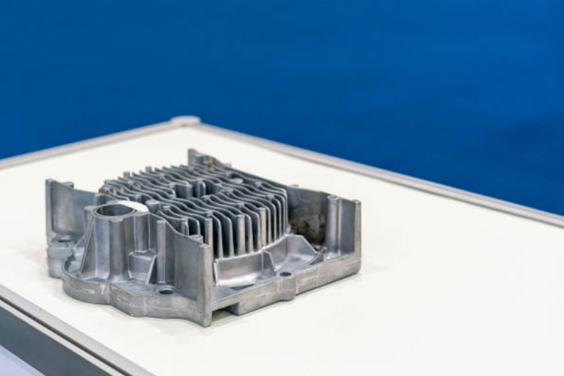
Important design features for zinc die casting components include wall thickness, draft, fillets, ribs, bosses, parting line location, gate planning, ejector marks, machining allowance, surface finish zones, and inspection datums. The practical RFQ problem is to review these design features before tooling so Neway can evaluate mold feasibility, defect risk, secondary operations, cost, and production inspection for custom zinc die cast components.
Which design features should buyers review before zinc die casting tooling?
Buyers should review the features that affect metal flow, ejection, dimensional control, appearance, and assembly. These features include wall thickness, transitions, ribs, bosses, holes, threads, clips, latch surfaces, cosmetic faces, draft direction, parting line, gate marks, ejector marks, and machined datums.
The design review should happen before tooling release because tool changes can affect cost and schedule. A 3D CAD model shows geometry, while the 2D drawing should identify tolerances, GD&T, finish requirements, visible surfaces, critical dimensions, and inspection methods.
Zinc Die Casting Design Feature | Manufacturing Risk if Undefined | RFQ Detail to Provide |
|---|---|---|
Wall thickness and transitions | Can create fill risk, sink, distortion, or uneven cooling | 3D CAD, wall section notes, and critical thin-wall zones |
Draft and ejection direction | Can cause sticking, drag marks, or tool release issues | Draft direction, cosmetic surfaces, and acceptable ejector mark areas |
Ribs, bosses, and mounting pads | Can affect filling, strength, shrinkage, and assembly fit | Screw size, load direction, mating part data, and boss function |
Parting line, gates, and vents | Can affect flash, visible marks, filling, and trimming | Visible zones, functional edges, and surfaces that cannot accept marks |
Machined and inspected features | Can lead to unclear machining scope or missed quality checks | Datum structure, critical dimensions, threads, bores, and CMM needs |
How do wall thickness, ribs, bosses, and fillets affect manufacturability?
Wall thickness, ribs, bosses, and fillets affect how molten zinc fills the cavity and how the part releases from the tool. Balanced wall sections support more stable filling and reduce unnecessary risk around thin walls, heavy sections, and sharp transitions.
Ribs should support stiffness without creating excessive mass. Bosses should be designed around screw size, load direction, draft, and ejection. Fillets and radii help reduce sharp transitions that can concentrate stress or create filling issues. Buyers should identify which ribs and bosses are functional so Neway can review geometry and tooling direction.
For related geometry topics, see thin-wall and complex custom zinc die casting parts and common zinc die casting parts and components.
Why do draft, parting line, gates, and ejector marks matter?
Draft, parting line, gates, and ejector marks matter because they connect part design to mold construction. Draft helps the zinc die cast part release from the tool. The parting line affects flash and visible edges. Gates and vents affect filling behavior. Ejector marks affect appearance and functional surfaces.
Buyers should mark visible surfaces, mating surfaces, cosmetic faces, sealing faces, and functional edges before tooling review. If gate marks or ejector marks cannot appear on a surface, that surface should be identified in the RFQ. If a parting line crosses a visible or assembled surface, Neway may need to review tooling direction or trimming expectations.
Which features should be machined after zinc die casting?
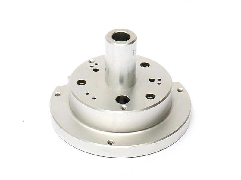
Features that control tight assembly fit, threaded engagement, sealing, bearing, flatness, or datum location may need machining after zinc die casting. Common examples include threaded holes, precision bores, flat mounting faces, hinge pin holes, connector seats, sealing surfaces, and datum pads.
Not every feature should be machined. Buyers should separate as-cast features from CNC-finished features so Neway can quote the right process scope. Over-machining can increase cost, while missing a critical machined feature can create assembly risk.
For cost and route planning, see zinc die casting cost considerations for custom metal parts and what buyers should provide for a custom zinc die casting quote.
Functional Feature | Likely Manufacturing Decision | Inspection Control |
|---|---|---|
Threaded holes | May need drilling, tapping, masking, or post-finish checks | Thread gauge, depth check, and drawing callout |
Mounting faces | May need machining if flatness or datum control is critical | CMM, flatness check, or functional gauge |
Connector openings | May need cast review, machining, or gauge validation | Position tolerance, mating part check, and visual inspection |
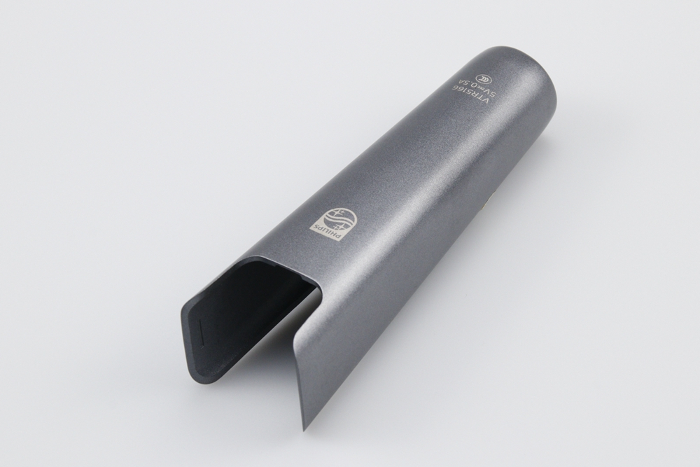
Cosmetic faces | May need controlled gate, ejector, polishing, plating, or coating plan | Visual standard, defect limit, and finish inspection |
Hinge or latch areas | May need strength review, wear review, and functional testing | Assembly test, cycle requirement if applicable, and contact surface check |
How should surface finish and inspection needs be shown on the drawing?
Surface finish and inspection needs should be shown directly on the 2D drawing. Buyers should mark visible faces, plated or painted surfaces, masked areas, burr limits, roughness needs, cosmetic criteria, critical dimensions, datum references, and inspection report requirements.
This drawing clarity helps Neway connect tooling, trimming, polishing, plating, painting, machining, and final inspection. If a feature must be checked after coating or plating, the drawing should state that final condition. If a cosmetic surface cannot show gate or ejector marks, the drawing should identify that surface before tooling design.
Related quality and finish guidance includes surface finishes available for zinc die cast parts, inspection before zinc die cast component shipment, and prevention of common zinc die casting defects.
What RFQ details help Neway review zinc die casting design?
Neway can review zinc die casting design more accurately when the RFQ includes 3D CAD, 2D drawing, part application, zinc alloy requirement, annual volume, critical features, visible surfaces, finish requirement, machined features, assembly interface, inspection method, packaging needs, and target production stage.
Buyers should state the design risk directly. If the risk is thin-wall filling, identify thin sections. If the risk is appearance, identify cosmetic faces. If the risk is assembly, provide mating part data. If the risk is inspection, define datums and critical dimensions. This lets Neway connect design features to tooling, process control, secondary operations, and quote scope.
For material and prototype planning, see which zinc alloy fits custom zinc die casting parts and whether zinc die casting can be used for prototype parts.
Related FAQs