Are there any specific design considerations to consider when planning for overmolding production?
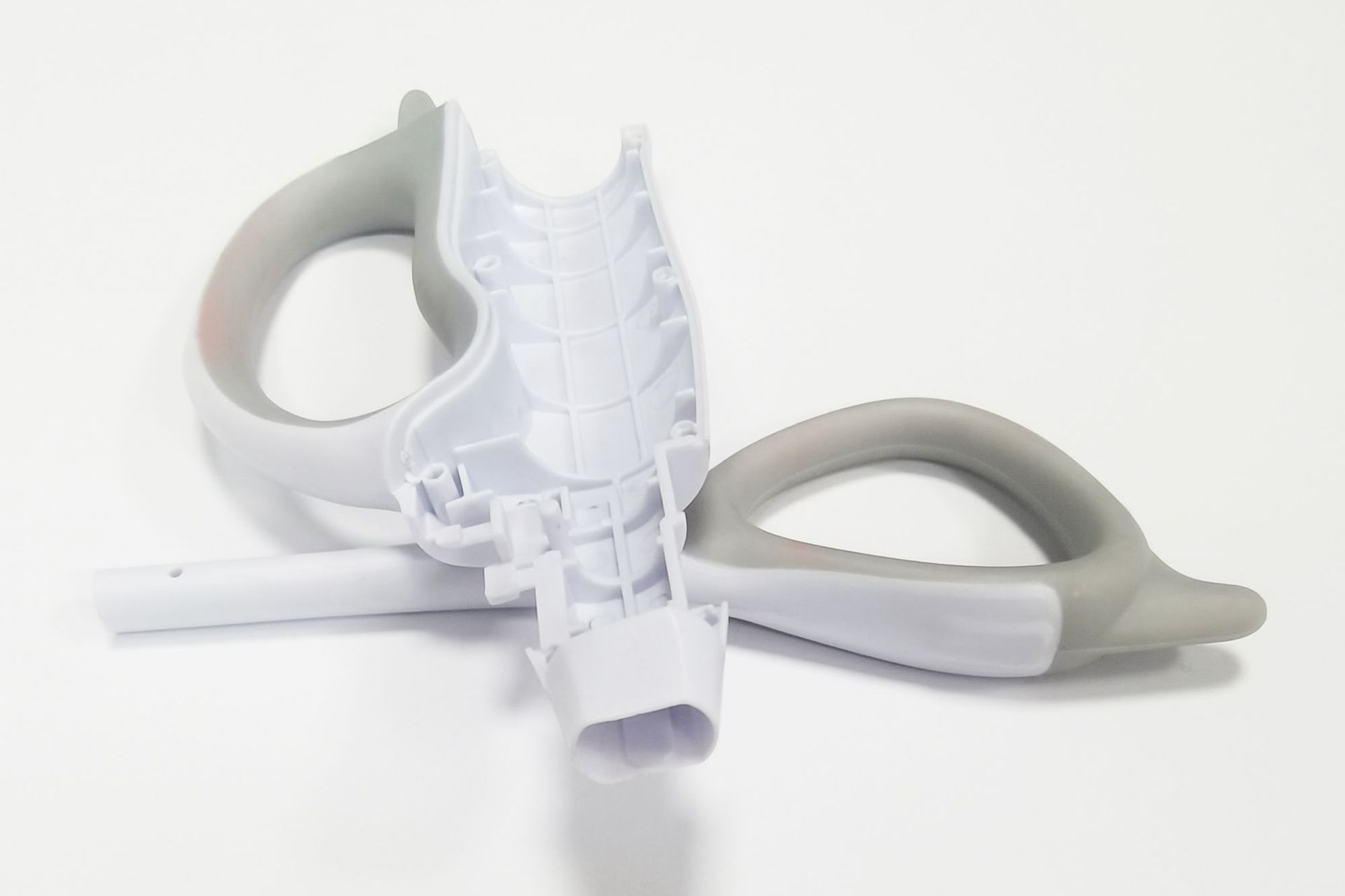
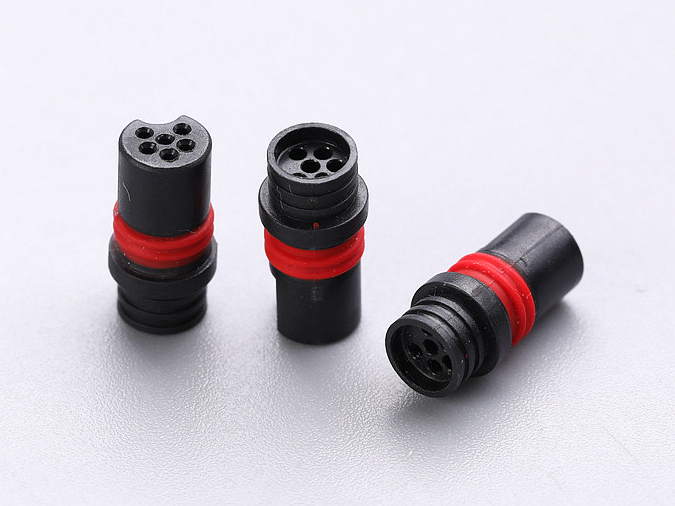
Specific design considerations for overmolding production include material compatibility, substrate geometry, mechanical locking features, overmold wall consistency, gate and parting-line location, insert positioning, bonding validation, and inspection planning. This FAQ helps buyers prepare overmolded grips, housings, buttons, seals, connectors, handles, and protective covers for quotation. The practical RFQ problem is making sure the part design can be molded, bonded, inspected, and scaled before the buyer commits to tooling.
Are there specific design considerations for overmolding production?
Yes. Overmolding requires design decisions that are more connected than a single-material molded part because the rigid substrate and soft overmold must function as one component. A strong overmolding design defines how the first material is held, how the second material flows, how the two materials bond, and how the final part will be inspected.
The buyer should review overmolding design before the RFQ is treated as a production quote. Early design review can identify material incompatibility, weak bonding surfaces, flash risk, trapped air, warpage risk, poor insert location, and cosmetic conflicts before tooling cost is committed.
How should material compatibility be designed for overmolding?
Material compatibility should be confirmed before the tool plan is finalized. Rigid substrates such as polycarbonate PC, ABS, nylon PA, PBT, or selected metal inserts may be overmolded with soft materials such as TPE or TPV and TPU. The selected material pair must support the required bonding method, process temperature, hardness, shrinkage behavior, color, and use environment.
If chemical adhesion is uncertain, the design may need mechanical locking. Undercuts, through-holes, grooves, ribs, textured areas, and wraparound edges can help the overmold grip the substrate. Buyers should clearly state whether the overmolded feature must resist peeling, sliding, twisting, compression, cleaning chemicals, heat, or repeated handling.
What substrate features help overmolding stay stable?
The substrate must be designed so it can be located securely during the overmolding shot. Poor substrate positioning can cause uneven overmold thickness, flash, short shots, cosmetic mismatch, or functional misalignment. Datum surfaces, locating holes, support ribs, shutoff areas, and controlled contact surfaces help the mold hold the substrate consistently.
For insert overmolding, buyers should identify insert material, insert tolerance, critical alignment features, and any surfaces that cannot be damaged during molding. If the substrate is produced by plastic injection molding, the first-shot shrinkage and warpage must be considered because the second-shot tool depends on the actual substrate shape.
How should wall thickness, flow, and shrinkage be controlled?
Overmold wall thickness should be designed for stable filling and consistent function. Very thin soft sections may create short-shot risk, while very thick sections may increase sink, cooling time, deformation, or inconsistent surface feel. The overmold flow path should also avoid trapped air, sharp flow restrictions, and unnecessary weld-line risk near functional surfaces.
Shrinkage differences between the substrate and overmold material can affect fit, flatness, sealing lips, button feel, and assembly clearance. Buyers should identify functional dimensions, cosmetic surfaces, and sealing surfaces in the drawing so the supplier can review gate location, venting, cooling, and inspection strategy.
Where should gates, parting lines, and shutoffs be placed?
Gate, parting-line, and shutoff placement should protect functional and visible surfaces. A gate mark on a cosmetic grip area, flash near a sealing edge, or a parting line on a user-contact surface can create rejection risk even if the part fills correctly. These features should be discussed before tool design starts.
For RFQ clarity, buyers should mark Class A cosmetic surfaces, grip areas, sealing surfaces, electrical contact areas, and assembly datums. The manufacturer can then recommend gate positions, venting, texture direction, and shutoff design that fit the part function instead of guessing from CAD alone.
Which overmolding design risks should buyers check before tooling?
Buyers should check whether the design has enough bonding area, enough mechanical retention, realistic overmold thickness, stable insert support, accessible inspection features, and clear cosmetic standards. A design that looks simple in CAD may still be difficult to mold if the soft material must flow around thin ribs, sharp corners, deep undercuts, or poorly supported inserts.
Design consideration | Buyer question to answer | Manufacturing risk if undefined |
|---|---|---|
Material compatibility | Which substrate and overmold grades are approved? | Poor adhesion, peeling, warpage, or process instability |
Mechanical locking | Does the design need grooves, holes, undercuts, or wraparound edges? | Soft material may separate under load or repeated handling |
Substrate location | How will the first-shot part or insert be held in the second-shot mold? | Misalignment, flash, uneven thickness, or damaged inserts |
Overmold thickness | Which areas are functional, cosmetic, sealing, or cushioning surfaces? | Short shots, sink, deformation, or inconsistent feel |
Gate and parting line | Which surfaces cannot show gate marks, flash, or parting lines? | Cosmetic rejection or interference with sealing and assembly |
Inspection plan | Which dimensions, bond tests, and visual standards must be checked? | Unclear acceptance criteria during sampling or production |
What RFQ information supports overmolding design review?
A useful overmolding RFQ should include 3D CAD, 2D drawings, substrate material, overmold material, hardness target, color target, texture requirement, annual volume, prototype quantity, bonding expectations, insert requirements, critical dimensions, cosmetic surfaces, sealing surfaces, and test requirements. Buyers should also state whether the project is for prototype validation, bridge production, or high-volume production.
This information helps the manufacturer review the design as a manufacturing system. Clear design inputs allow the supplier to recommend material trials, geometry changes, tooling strategy, inspection methods, and production controls before a mold is built.
Related FAQs
Which materials are best suited for the overmolding process?
What factors should be considered when selecting materials for Over Molding?
What types of materials can be effectively used in over-molding?
Are there any limitations or challenges associated with overmolding?
When to select overmolding for plastic injection molding projects?
Is over-molding suitable for both low and high-volume production?