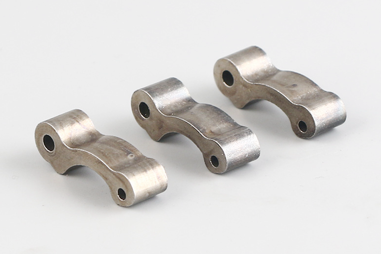
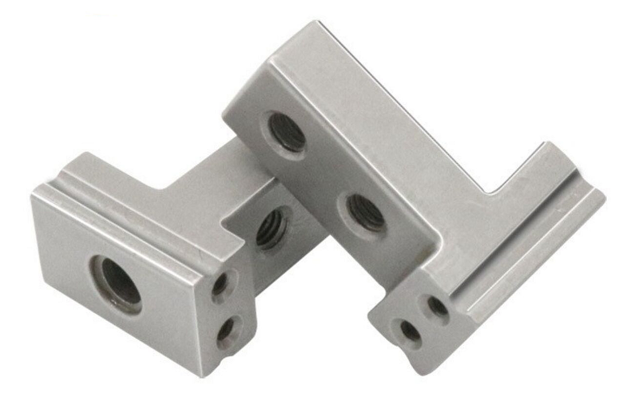
Which surface treatments best ensure long-term stability for RF connectors?
RF connector surface treatment should be selected by contact resistance, corrosion exposure, fretting wear, shielding continuity, and compatibility with the MIM base alloy. This FAQ explains how metal injection molding, stainless steel MIM materials, polishing, electropolishing, conductive electroplating, and environmental validation affect RF connector bodies, contact housings, shield shells, and telecommunication module interfaces. The practical RFQ problem is to define which connector surfaces carry RF current, which surfaces need corrosion protection, and which inspection tests prove stable electrical performance after production.
Which RF connector surfaces need functional treatment?
RF connector drawings should separate conductive contact surfaces, grounding surfaces, shielding interfaces, wear surfaces, and cosmetic or handling surfaces. These areas do different jobs, so a single surface treatment note is usually not enough for a high-frequency connector.
Conductive contact areas need controlled surface roughness, clean plating, and stable contact resistance. Grounding lands and shield shells need continuous metal-to-metal contact across the connector assembly. External stainless steel areas need corrosion resistance and wear control without creating an insulating layer on RF current paths. For telecommunication connectors, this separation helps Neway review which surfaces must be masked, plated, polished, or inspected separately.
RF connector surface entity | Function in the assembly | Surface treatment concern |
|---|---|---|
Contact pin seat or socket area | Carries signal or ground current | Low contact resistance, clean plating, and controlled roughness |
Shielding shell or grounding land | Maintains EMI shielding continuity | Plating coverage, flatness, burr control, and assembly pressure |
Thread, snap-fit, or mating feature | Controls repeated assembly engagement | Fretting wear, plating adhesion, and dimensional buildup |
External connector housing | Protects the RF interface from handling and environment | Corrosion resistance, cleaning compatibility, and visual consistency |
Which MIM materials affect RF connector surface stability?
The MIM material affects surface treatment because the base alloy determines corrosion behavior, mechanical support, magnetic behavior, and coating compatibility. MIM 17-4 PH may be reviewed for strong connector housings and shield shells, while MIM 316L may be reviewed when stainless steel corrosion resistance is important. MIM Fe-50Ni may be considered when magnetic shielding behavior is part of the connector design discussion.
For RF current paths, the base MIM alloy is often not the only electrical surface. Buyer-specified copper, nickel, silver, gold, or multilayer plating may be used to create a more conductive and stable contact surface. The RFQ should identify the coating stack, the surfaces that need the coating, and any areas where coating buildup would interfere with thread fit, latch engagement, or connector mating.
When should polishing or electropolishing be used before plating?
Polishing or electropolishing should be reviewed when RF contact areas, shield lands, or internal connector surfaces need lower roughness before conductive plating. Surface irregularities can increase local contact variation, trap contamination, or reduce plating uniformity.
For MIM RF connectors, surface preparation must respect both geometry and function. Aggressive finishing can round grounding edges, open small slots, or change fit-up surfaces. Insufficient finishing can leave asperities, burrs, or oxide conditions that make contact resistance less stable. Neway reviews surface preparation together with surface finishing requirements, MIM shrinkage behavior, and the planned electroplating route.
Which electroplating controls support stable RF performance?
Electroplating controls RF connector stability by managing conductive layer material, thickness, adhesion, porosity, masking, and coverage on contact surfaces. The plating stack must be selected for the connector environment and the RF function, not only for appearance.
Nickel underlayers may be used as a barrier or wear-support layer, while copper, silver, or gold layers may be specified by the buyer for conductive surfaces. The correct choice depends on mating material, insertion cycle requirement, humidity exposure, temperature exposure, galvanic corrosion risk, and buyer-approved electrical testing. If a coating is too thick, connector mating dimensions may change. If a coating is discontinuous, RF current paths or shielding interfaces may become unstable.
Surface treatment entity | RF connector use case | Inspection focus |
|---|---|---|
Electropolishing | Prepare stainless steel contact-adjacent surfaces before plating | Roughness, edge condition, and dimensional change |
Nickel underlayer | Support adhesion, wear resistance, or diffusion control | Thickness, adhesion, continuity, and masking boundary |
Copper, silver, or gold conductive layer | Reduce contact resistance on RF current paths | Coverage, porosity, contact resistance, and environmental stability |
Localized masking | Keep coating away from threads, datum faces, or press-fit zones | Boundary accuracy and post-plating fit-up |
How should RF connector surface treatments be validated?
RF connector validation should combine coating inspection, dimensional inspection, contact resistance testing, RF testing, and environmental exposure testing. A coating can look acceptable while still causing unstable signal behavior if the coating is porous, too rough, poorly bonded, or inconsistent across grounding interfaces.
Neway can review coating thickness measurement, adhesion checks, visual inspection, roughness measurement, CMM inspection, and functional tests with the buyer. For RF performance, buyers often compare insertion loss, return loss, contact resistance, and shielding continuity before and after humidity, thermal cycling, salt spray, vibration, or insertion cycle tests. The exact test method should come from the buyer drawing, assembly standard, or product validation plan.
How do surface treatments change the RFQ for MIM RF connectors?
Surface treatments change the RFQ because Neway must quote the MIM part, surface preparation, plating route, masking, inspection, and validation plan together. A drawing that only says "plated" does not give enough information for RF connector risk review.
A useful RFQ should include the MIM material grade, 3D CAD model, 2D drawing, frequency range, contact resistance target, shielding requirement, surface roughness target, plating stack, plating thickness range, masking zones, mating part material, insertion cycle expectation, environmental exposure, and inspection sample plan. If a connector shares geometry with an RF cavity or shield housing, the buyer should also define which datum surfaces control assembly fit and which surfaces are allowed to receive secondary machining.
Related FAQs
How to design and control RF cavities to ensure resonance and shielding?
How to balance conductivity, heat, weight, and cost when selecting RF materials?
How does Neway ensure precision of RF dimensions in mass production?
What steps take RF components from prototype to full-scale production?
What surface finishes are available for custom stainless steel MIM parts?