What Is The Progressive Die Stamping Process And How Does It Work?
Progressive Die Stamping RFQ Decision for High-Volume Sheet Metal Parts: Progressive die stamping is a sheet metal stamping process that feeds coil stock through a die with multiple stations to produce pierced, blanked, bent, formed, and cut-off metal parts in sequence. This article explains how the progressive die stamping process works, where the process fits brackets, clips, terminals, shields, contact parts, and other repeatable stamped components, and what practical RFQ details buyers should confirm before tooling review.
Progressive die stamping is most useful when the part geometry can stay connected to a carrier strip while each station adds a controlled feature. The manufacturing decision is not only whether a press can form the part; the buyer also needs to confirm material grade, sheet thickness, temper, grain direction, burr direction, functional datums, annual demand, surface requirements, and inspection expectations before a stamping quote can be reviewed with confidence.
How Progressive Die Stamping Feeds Coil Stock Through Multiple Die Stations
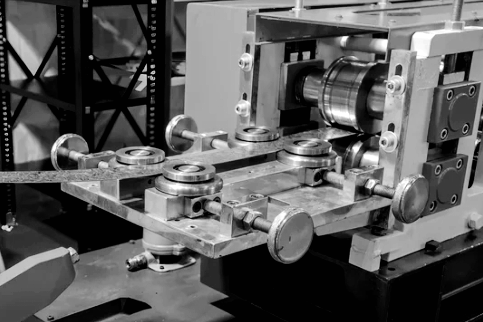
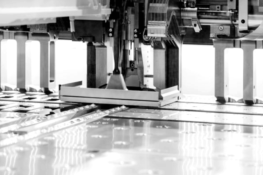
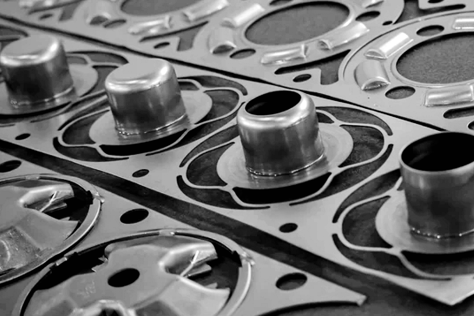
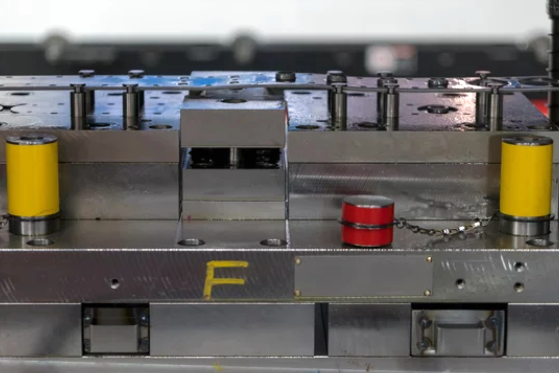
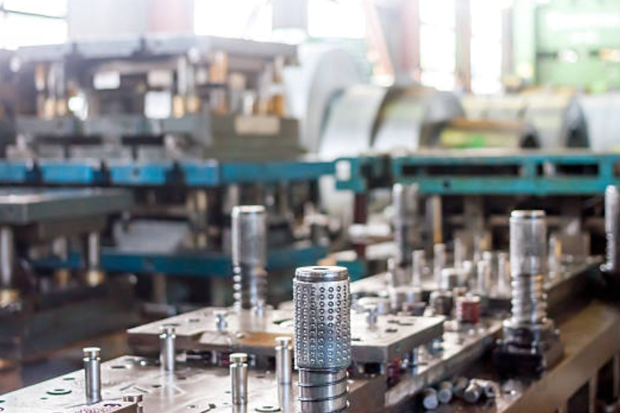
Progressive die stamping uses a coil-fed strip, a press, and a progressive die that contains several stations in one tool. Each press stroke advances the strip by a defined feed pitch. As the strip moves forward, station one may pierce pilot holes, later stations may blank edges, form bends, coin features, emboss ribs, or pierce functional openings, and the final station separates the finished stamped part from the carrier strip.
The key difference from single-operation stamping is that progressive die stamping builds several features during continuous strip movement. The strip remains attached to a carrier until cutoff, so the die must control strip progression, part location, scrap removal, and feature sequence. If a drawing has many small holes, tabs, louvers, retaining clips, or shallow formed features, the strip layout often decides whether progressive die stamping is practical.
Buyers should treat the strip layout as a manufacturing decision, not only a tooling detail. Carrier width, web strength, pilot-hole location, scrap bridges, bend sequence, and cutoff direction can affect material usage, dimensional repeatability, burr orientation, and how inspection datums are maintained through production.
Why Progressive Die Stamping Fits Repeatable High-Volume Sheet Metal Parts
Progressive die stamping fits repeatable sheet metal parts when tooling investment can be supported by recurring demand and stable part geometry. The process can reduce part handling because piercing, blanking, forming, and cutoff happen within a coordinated die set. That makes progressive die stamping a strong candidate for electrical terminals, spring contacts, clips, shields, flat brackets, washers, retainers, latch parts, and other compact metal components.
The practical advantage is repeatability through a controlled station sequence. A well-planned progressive die can keep features located from the same strip datum as the part moves through the die. However, progressive die stamping is not automatically the best route for every stamped part. Deep cups, very large panels, severe draws, thick section changes, frequent design revisions, or low-volume prototypes may point to another route such as laser cutting with bending, transfer die stamping, deep drawn metal stamping, or CNC machining for early validation.
Progressive Die Stamping Workflow From Strip Layout to Cutoff
The progressive die stamping workflow starts before the press run. The drawing, material specification, part function, and expected demand are reviewed to decide whether the part can travel through stations while attached to a carrier strip. The tool design then defines pilot holes, station sequence, scrap channels, forming clearances, and cutoff method.
During production, coil stock is fed into the press and guided into the die. Each stroke performs one or more operations while the feeder advances the strip by one pitch. The part may be pierced at early stations, shaped across forming stations, and separated after the final operation. When the process is stable, the same station sequence repeats continuously for each part position along the strip.
Process Stage | What Happens in Progressive Die Stamping | Manufacturing Risk to Control | RFQ Information Needed |
|---|---|---|---|
Drawing and part review | Functional surfaces, holes, bends, tabs, and cosmetic areas are identified. | Datums, burr direction, and critical features may be unclear. | 2D drawing, 3D model, material grade, thickness, and acceptance criteria. |
Strip layout and station plan | The part remains attached to a carrier strip while each station adds features. | Weak carriers, poor scrap flow, or an unsuitable bend sequence can cause instability. | Annual demand, part orientation limits, grain direction, and surface side requirements. |
Piercing and blanking | Punches create holes, slots, notches, and outside profiles. | Burrs, slug pulling, edge rollover, and hole distortion can affect assembly. | Hole function, mating hardware, deburring requirement, and inspection method. |
Bending and forming | Stations form tabs, offsets, ribs, lances, embosses, and shallow profiles. | Springback, cracking, tool marks, and feature interference may occur. | Bend angle requirement, inside radius, material temper, and functional fit. |
Cutoff and collection | The finished part is separated from the strip and removed from the die area. | Cutoff burrs, deformation, or part mixing can affect downstream operations. | Packaging requirement, lot traceability, surface protection, and quantity plan. |
Design and Material Factors That Affect Progressive Die Stamping RFQs
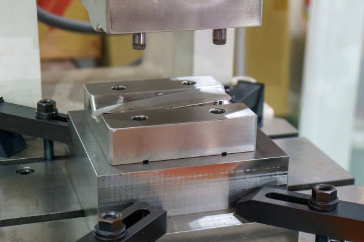
The strongest RFQ packages for progressive die stamping define the part function as well as the drawing geometry. Material grade and temper affect formability, springback, edge cracking risk, and tool wear. Stainless steel, carbon steel, spring steel, aluminum, brass, copper, and phosphor bronze can all be considered for stamped parts, but each material family behaves differently during piercing, forming, and surface finishing.
Feature design also matters. Small holes near bends, narrow tabs, sharp internal corners, shallow embosses, and close hole-to-edge distances can create tool-strength or distortion risks. A drawing should identify which dimensions are functional, which surfaces are cosmetic, which edge direction can carry burrs, and which areas may accept tool marks. Without that information, a supplier may quote a tool that makes the shape but does not protect the actual assembly requirement.
Secondary operations should be discussed early because they may change the strip layout or part orientation. Common follow-up operations for stamped parts include deburring, tumbling, cleaning, tapping, riveting, welding, plating, passivation, anodizing for aluminum, heat treatment for spring behavior, and assembly. If plating thickness, masking, conductivity, corrosion resistance, or cosmetic side matters, those requirements should be stated before tooling release.
Progressive Die Stamping Compared With Deep Drawing, Transfer Die Stamping, and Multi-Slide Forming
Progressive die stamping is one of several metal stamping routes. The best route depends on geometry, feature depth, part size, handling method, and production stage. Buyers can use the comparison below to decide whether a part should stay on a carrier strip, be transferred between stations, be drawn into a deep cup shape, or be formed with multi-slide tooling.
Stamping Route | Suitable Part Type | Key Manufacturing Limitation | Buyer Decision Before Quotation |
|---|---|---|---|
Progressive die stamping | Repeatable flat or shallow formed parts with holes, tabs, bends, and cutouts. | The part must remain stable on a strip until cutoff. | Confirm demand, strip orientation, burr side, and functional datums. |
Deep drawn metal stamping | Cups, cans, shells, sleeves, and hollow shapes with significant draw depth. | Material flow, wrinkling, thinning, and draw ratio control become central. | Confirm depth, radius, wall thinning allowance, and material ductility. |
Transfer die stamping | Larger or more three-dimensional stamped parts moved between stations. | Transfer handling and station location must be controlled between operations. | Confirm part size, handling surfaces, feature access, and volume plan. |
Multi-slide metal stamping | Small clips, contacts, wire-form-like parts, and components with bends from several sides. | Part geometry must fit the forming slide arrangement and material feeding method. | Confirm bend directions, material strip width, and spring-back acceptance. |
When Deep Drawn Metal Stamping May Be Better
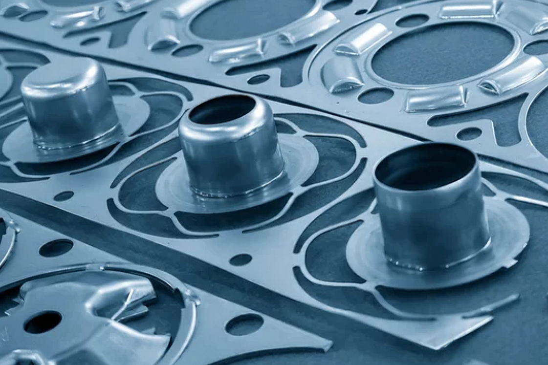
Deep drawn metal stamping may be better when the main part feature is a cup, shell, sleeve, or enclosed cavity. The engineering problem shifts from station-to-station feature creation to controlled material flow. If the part needs significant depth, smooth walls, and controlled thinning, the RFQ should focus on draw sequence, radius design, material ductility, and trimming allowance.
When Transfer Die Stamping May Be Better
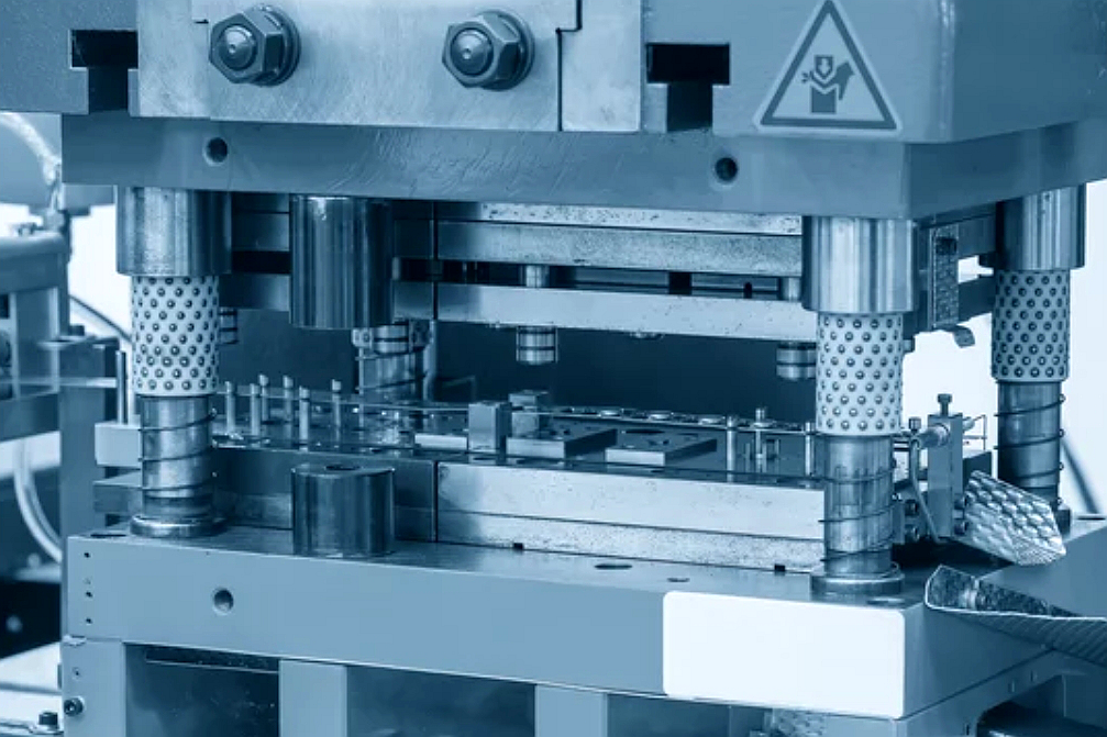
Transfer die stamping may be better when the part cannot remain attached to a carrier strip or when the geometry needs more room between operations. Transfer dies move the part from station to station, so they can support larger shapes or forms that would be difficult to keep stable on a progressive strip. Buyers should define handling surfaces, critical appearance areas, and datum requirements before transfer tooling review.
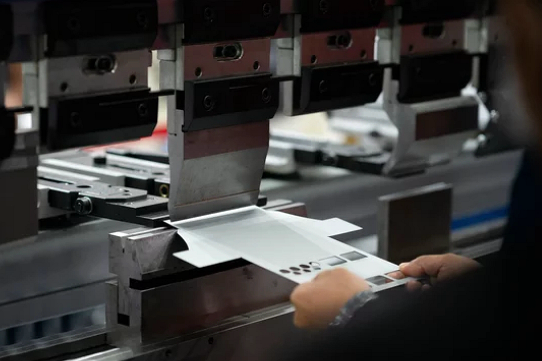
When Multi-Slide Metal Stamping May Be Better
Multi-slide metal stamping may be better for compact clips, contacts, springs, and small formed components that require bending from several directions. The route can be practical when the part is narrow, the strip can feed cleanly, and the forming actions are better handled by multiple slides than by a conventional progressive die layout.
Inspection, Secondary Operations, and Production Evidence for Progressive Stamped Parts
Progressive die stamping inspection should match the function of the stamped part. Functional holes, bend angles, flatness, tab height, edge condition, and mating dimensions may need different checks. Depending on the drawing and acceptance criteria, inspection evidence may include first article inspection, dimensional reports, optical inspection, CMM checks for selected features, go/no-go gauges, visual standards for burrs and surface marks, coating thickness reports, hardness checks after heat treatment, or packaging inspection.
Production evidence is especially important when a small dimensional shift can affect assembly. Tool wear, punch chipping, feed misalignment, material lot variation, and springback changes can all influence stamped part consistency. For recurring production, buyers should define how critical dimensions are monitored, what defects require containment, and which records need to accompany each shipment.
Secondary operations should be controlled as part of the same manufacturing route. A stamped contact may need plating and conductivity checks. A stainless bracket may need passivation or deburring. A spring clip may need heat treatment or stress relief subject to the material specification. A cosmetic stamped cover may need surface protection during packaging. These steps should be included in the RFQ because they affect cost, timing, inspection scope, and acceptance criteria.
What Neway Precision Reviews Before Progressive Die Stamping Production
For a progressive die stamping review, Neway Precision needs enough information to evaluate part geometry, tooling approach, material behavior, secondary operations, and inspection scope. A complete RFQ usually includes the 2D drawing, 3D model if available, material grade and temper, sheet thickness, expected quantity or demand pattern, functional datums, critical dimensions, burr-side preference, surface finishing requirement, assembly use, and required inspection records.
If the part is still being developed, prototype or pilot-stage manufacturing may use a different route before progressive die tooling is released. Laser cutting, CNC bending, soft tooling, or simplified stamping may help validate fit before production tooling. Once the design is stable and the production need is clear, progressive die stamping can be reviewed for coil-fed production, tool maintenance planning, and repeatable lot control.
Related FAQs
What Is Progressive Stamping And How Does It Benefit High-Volume Production?
13 Mechanical Design Considerations For Metal Stamping Parts
What Are The Common Defects In Sheet Metal Stamping And How Can They Be Prevented?
What Are The Common Issues Encountered During Mass Production Metal Stamping?
Why Is Regular Tooling Maintenance Critical In High-Volume Metal Stamping Processes?