What is An Example of Insert Molding?
What is an example of insert molding?
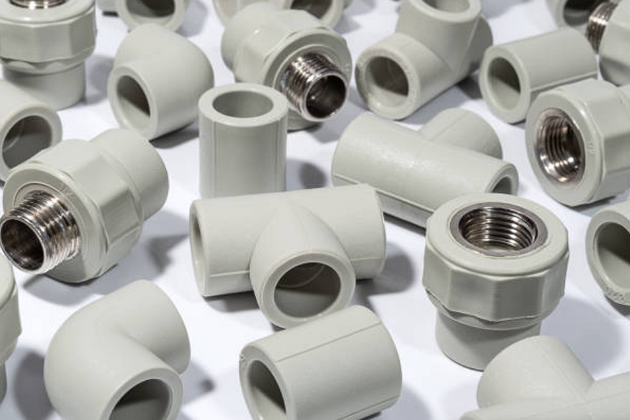
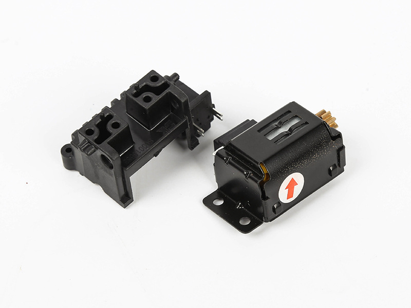
A common example of insert molding is an electrical connector where metal pins, terminals, or contacts are placed into the mold and encapsulated by injection molded plastic. The practical RFQ problem is confirming whether the insert location, plastic material, insulation requirement, pull-out strength, dimensional tolerance, and inspection method can be controlled during molding.
In this type of part, the metal insert provides electrical function and mechanical interface, while the molded plastic housing provides insulation, positioning, protection, strain relief, and assembly geometry. The process can reduce separate assembly steps, but it also creates tooling and process risks around insert alignment, flash, resin flow, and insert retention.
How does an electrical connector use insert molding?
Electrical connector insert molding begins with pre-made metal contacts or pins. The contacts are loaded into the mold by manual loading, fixture loading, or automation depending on production requirements. Plastic is then injected around the contacts to form the connector body, insulation wall, latch, keying feature, seal support, or strain-relief geometry.
The insert must remain in the correct position while molten plastic flows around it. If the insert moves, tilts, or is not fully supported, the connector may fail dimensional inspection or mating function. The RFQ should define pin position, exposed contact areas, insulation distance, housing material, mating geometry, and inspection method.
Why use insert molding for connectors?
Insert molding is used for connectors when the plastic body must precisely hold metal contacts, protect conductive areas, reduce separate assembly, or improve retention around pins and terminals. It can create a compact part with molded alignment features, clips, ribs, housings, and insulation walls around the metal insert.
The benefit depends on the design. A connector with simple geometry and low volume may be assembled from separate parts. A connector with high alignment requirements, repeated production, or protected metal contacts may justify insert molding. Buyers should compare tooling cost, insert placement control, inspection needs, and the functional risk of the connector.
What materials are common in connector insert molding?
The plastic housing may use engineering resins such as PBT, PA, PPS, PC, ABS-PC, LCP, or other materials depending on heat exposure, electrical insulation, dimensional stability, chemical exposure, and assembly requirements. The metal insert may use copper alloy, brass, stainless steel, plated contacts, stamped terminals, or machined pins depending on conductivity, corrosion behavior, strength, and mating cycle requirements.
The buyer should specify resin grade, flame rating if required, color, contact plating, insert thickness, insert tolerance, and whether the insert has holes, knurls, grooves, or mechanical retention features. Material compatibility matters because molding heat and pressure can affect plating, contact alignment, and insert retention.
What defects should be controlled in insert molded connectors?
Common risks include insert shift, exposed metal where insulation is required, flash around contacts, short shots behind inserts, voids, burn marks, warpage, and poor plastic flow around tight insert geometry. The mold may need shut-offs, insert supports, vents, controlled gate location, and ejection planning to protect the insert and the molded housing.
Inspection should match the connector function. Dimensional inspection may check pin position, housing size, latch geometry, mating interface, and critical datum surfaces. Functional inspection may include continuity, insulation resistance, pull-out test, torque test, mating test, or leak test when the connector must seal.
How is insert molding different from overmolding in this example?
In the connector example, insert molding places a metal contact into the mold before the plastic housing is formed. Overmolding would usually mean molding a second material over an existing connector body or cable assembly to add sealing, strain relief, grip, insulation, or protection. Both processes can appear in connector manufacturing, but they solve different problems.
Buyers should define whether the project requires embedded contacts, a molded seal, a cable strain-relief feature, or a soft protective shell. A connector may use insert molding for the metal contacts and overmolding later for cable strain relief or environmental protection, subject to design and testing requirements.
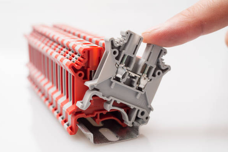
Connector Feature | Insert Molding Role | Manufacturing Risk | Inspection Evidence |
Metal pins or terminals | Encapsulated and positioned inside the molded plastic connector body | Insert shift, plating damage, exposed metal, or poor retention | Pin position check, pull-out test, continuity test, and visual inspection |
Plastic housing | Provides insulation, mating geometry, latch features, and structural support | Short shot, flash, warpage, burn marks, or mating mismatch | Dimensional report, go/no-go gauge, visual standard, and mating test |
Seal or strain relief | May be molded as part of the housing or added later by overmolding | Leak path, uneven compression, weak bond, or cable movement | Leak test, pull test, bend test, or buyer-defined functional test |
Assembly interface | Controls how the connector fits with another part or harness | Datum mismatch, tolerance stack-up, latch failure, or interference | CMM report, mating-force check, latch test, and assembly inspection |
What should buyers provide for an insert molded connector RFQ?
A useful RFQ should include the connector drawing, 3D model, insert drawing, insert material, contact plating, resin grade, exposed contact areas, pin position tolerance, mating requirement, insulation requirement, pull-out or torque requirement, sealing requirement, expected quantity, and inspection method.
This information helps the manufacturer decide how to locate inserts, design shut-offs, control resin flow, prevent flash, and verify the final connector function.
Related FAQs