Metal Injection Molding Parts: Design, Materials, Tolerances, and Cost Factors
For buyers evaluating Metal Injection Molding (MIM), the real question is rarely whether the process exists. The practical question is whether a specific part is suitable for MIM from a design, material, tolerance, and cost standpoint. In most projects, the answer depends on how small and complex the geometry is, how critical the final dimensions are, what alloy performance is required, and whether the expected volume is high enough to justify tooling and sintering-based production.
MIM is especially valuable because it can produce small metal components with complex geometry that would otherwise require long CNC cycle times, multi-step assembly, or high material waste. But MIM is not a universal solution. A part that is too large, too simple, or too dependent on extremely tight all-over machined tolerances may not be the best fit. That is why engineering buyers should evaluate MIM parts through six linked topics: part suitability, design rules, material selection, shrinkage and dimensional control, cost structure, and mass-production consistency.
What Types of Parts Are Suitable for MIM
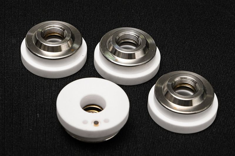
MIM is most suitable for small metal parts that combine complex geometry with medium or high production quantity. Typical successful parts include miniature gears, cams, latches, pawls, lock parts, medical fittings, compact brackets, electronic structural inserts, trigger components, and other dense-feature components that are difficult to machine efficiently from bar stock. In these cases, MIM converts geometric complexity into tooling rather than repeated machining time.
The process is especially attractive when the part includes multiple design elements such as thin walls, fine serrations, small holes, curves, ribs, or compact 3D geometry that would raise machining cost sharply in volume production. Buyers should think of MIM as a process for high-feature-density small components rather than a general replacement for all metal parts. If the part is simple and low volume, CNC machining may still be more practical. If the part is very large, another process is usually more appropriate.
Common Part Types That Fit MIM Well
Part Category | Why It Fits MIM | Typical Industries |
|---|---|---|
Miniature mechanical parts | High feature density and small size | Locks, electronics, power tools |
Precision structural inserts | Complex 3D forms with repeatable volume demand | Medical, electronics, automotive |
Small wear-related parts | Suitable for hardenable or wear-resistant alloys | Locks, tools, industrial equipment |
Compact corrosion-resistant parts | Strong fit for stainless steel MIM materials | Medical, electronics, fluid-contact applications |
Lightweight high-value metal parts | Can justify more advanced material systems | Medical and specialty engineering applications |
Wall Thickness, Small Features, Undercuts, Holes, and Complex Geometries
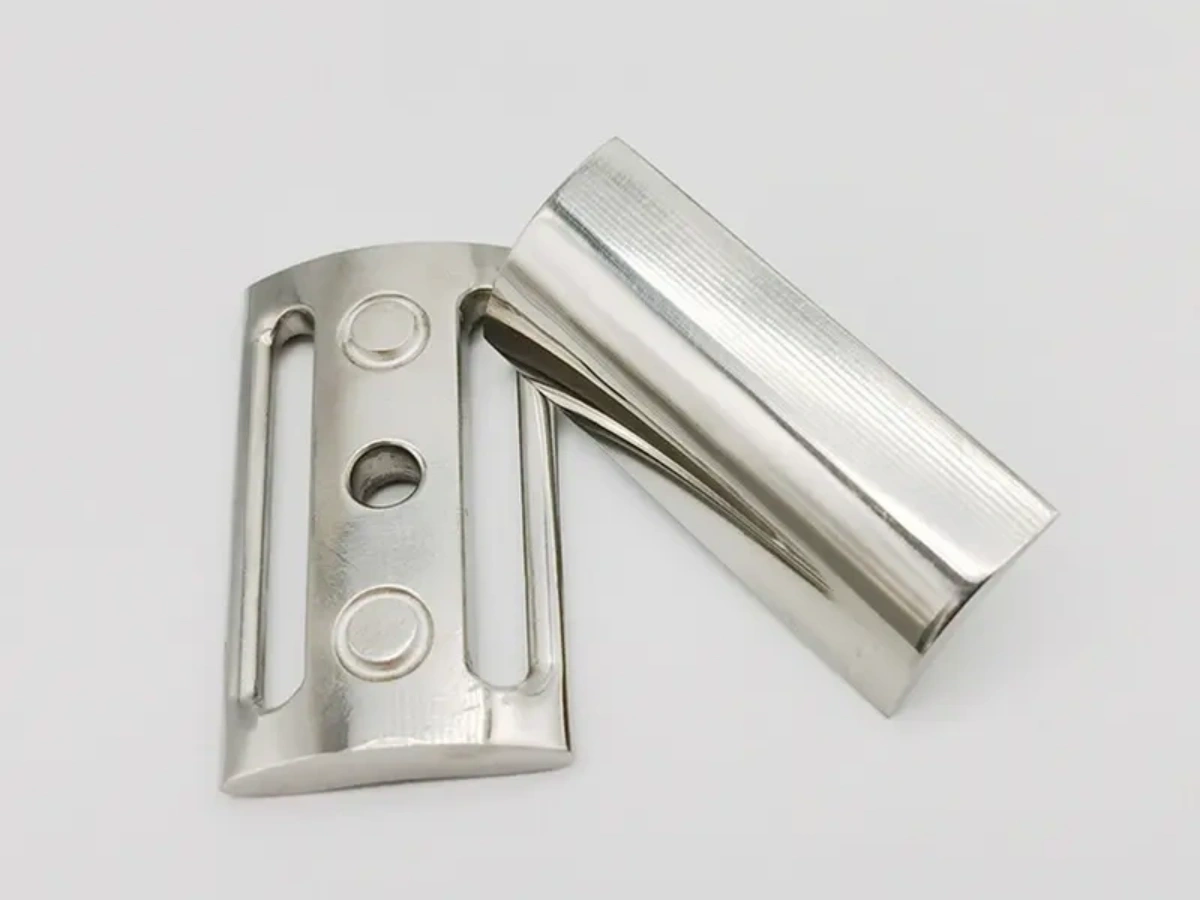
The biggest design strength of MIM is its ability to handle small, intricate geometries. Compared with conventional powder compaction, MIM supports much more shape freedom. Compared with machining, it can create multiple features in one molded part rather than by removing material across many operations. This makes it especially valuable for thin sections, compact profiles, fine teeth, and integrated functional details.
That said, good MIM design still requires discipline. Wall thickness should be reasonably balanced to support more uniform shrinkage during sintering. Sharp transitions in section mass can increase distortion risk. Small holes and fine features may be possible, but they must be evaluated in relation to debinding stability, tool manufacturability, and post-sinter dimensional behavior. Undercuts and complex forms can often be supported, but they influence tooling strategy and cost. The part should therefore be designed for MIM, not merely forced into it.
For many projects, the most efficient approach is to use MIM for the complex overall geometry and reserve only a few critical features for secondary machining. This allows the design to benefit from near-net-shape efficiency without forcing unnecessary process risk into the molded part.
Design Features and Their MIM Implications
Design Feature | MIM Advantage | What Buyers Should Review |
|---|---|---|
Thin walls | Supports compact lightweight metal parts | Wall balance and shrinkage stability |
Small holes | Can reduce drilling in volume production | Hole size stability and whether post-machining is needed |
Fine teeth / serrations | Good for small mechanical components | Tool detail quality and wear requirements |
Undercuts | Possible through tooling strategy | Impact on mold complexity and cost |
Complex 3D geometry | Strong MIM advantage over machining | Whether geometry is truly volume-efficient in MIM |
Mixed thick and thin sections | Possible but sensitive | Risk of distortion or differential shrinkage |
Material Selection for Strength, Corrosion Resistance, Wear Resistance, and Biocompatibility
Material selection in MIM should begin with application requirements rather than alloy familiarity. Buyers should first decide whether the part needs strength, corrosion resistance, hardness, wear life, low density, or biocompatibility. The correct material family can then be matched to the process. This is one reason Metal Injection Molding | Materials and Properties is such an important reference for engineering decisions.
For many industrial parts, stainless steels are the most common choice because they combine corrosion resistance with stable manufacturability. MIM 17-4 PH is often selected when higher strength and good corrosion resistance are both needed. MIM 316L is a common choice when corrosion resistance and cleaner-surface performance matter more. For lightweight or specialized high-value applications, MIM Ti-6Al-4V (Grade 5) is an important option. Other material families such as low alloy steels, cobalt-based alloys, and tungsten alloys serve more specialized structural, wear, density, or medical requirements.
Material Selection Logic for MIM Parts
Performance Need | Typical MIM Material Direction | Why Buyers Choose It |
|---|---|---|
General corrosion resistance | Suitable for medical, electronics, and clean-environment parts | |
High strength plus corrosion resistance | Strong fit for structural small components | |
Lightweight and high-value performance | Useful in advanced medical or specialty engineering parts | |
Mechanical strength and economy | Low alloy steel family | Good for gears, cams, and transmission-style parts |
Wear resistance / specialty service | Cobalt or hardenable alloy families | Useful where contact durability matters |
High density / specialty function | Tungsten alloy family | Selected for compact high-density part requirements |
Shrinkage and Dimensional Control in MIM
Shrinkage is one of the most important engineering realities in MIM. After molding, the part is still a green component containing binder. During debinding and sintering, the part densifies and shrinks into its final metal form. This shrinkage is not a defect. It is a core part of the process. But it must be predicted and controlled carefully through tooling, feedstock consistency, and furnace discipline.
For buyers, this means tolerance expectations should be set based on real process logic rather than assuming every feature will emerge as if machined. A strong MIM supplier should be able to explain which dimensions can remain as-sintered, which ones may need sizing or machining, and how shrinkage variation is controlled in mass production. That is why What Is The Shrinkage of Metal Injection Molding? is such a practical question in RFQ review.
Dimensional control in MIM depends on more than tool size. It is driven by feedstock quality, molding consistency, debinding stability, sintering atmosphere, furnace loading, and the geometry itself. Well-designed parts with balanced sections and clearly prioritized critical surfaces are much easier to control consistently than parts with abrupt thickness changes and unrealistic all-over tolerance expectations.
Cost Factors: Mold, Material Powder, Sintering, Machining, Surface Finish
The cost of a MIM part is driven by both upfront tooling and recurring production cost. Buyers often focus too much on powder price, but the real cost picture is broader. Mold design and tooling represent the largest initial investment. Material powder affects feedstock cost. Sintering is a major thermal-processing cost center. Secondary machining and finishing may add significant cost depending on the part’s functional requirements.
Compared with CNC machining, MIM often becomes more cost-effective when the part is small, complex, and produced in larger quantities. That is because MIM reduces repeated material removal and integrates more geometry into the molded form. But if the part is low volume, simple, or heavily dependent on machined critical features, CNC may still remain more practical. This is why buyers should compare route economics through total process logic rather than unit price alone. A useful internal reference is What cost advantages does the MIM process offer compared with CNC machining?
Main Cost Drivers in MIM Parts
Cost Factor | Why It Matters | Buyer Impact |
|---|---|---|
Mold / tooling | Upfront investment needed for production-ready geometry | Most important for launch cost and volume planning |
Metal powder | Feedstock quality and alloy type affect material cost | Important for premium alloys and high-performance parts |
Sintering | Thermal process drives densification and final structure | Major recurring process cost |
Secondary machining | Needed for critical datums or special features | Can increase cost if too many features require post-processing |
Surface finish | Polishing, passivation, or other finish steps add cost | Important where appearance or corrosion resistance is critical |
Production volume | Spreads tooling cost across total output | Determines whether MIM is commercially favorable |
How Neway Controls Consistency in Mass Production
For buyers, the real test of a MIM supplier is not whether one sample looks acceptable. It is whether the supplier can maintain consistency across batches. At Neway, MIM consistency control is built around the full route: tooling stability, feedstock control, molding consistency, debinding discipline, sintering repeatability, and defined secondary operations. This process-chain approach matters because a small drift in one stage can affect the final part significantly when the geometry is compact and feature-dense.
Mass-production consistency is especially important for parts used in medical devices, electronics, locks, automotive assemblies, and power tools where one unstable dimension can affect movement, fit, sealing, or durability. A reliable MIM supplier should therefore support not only manufacturing, but also clear dimensional logic and repeatable production conditions over time.
If the project requires supporting evidence for quality control, buyers may also want to confirm access to dimensional inspection tools such as CMM measurement, optical comparator inspection, or 3D scanning measurement depending on the part’s critical features.
Conclusion: How Buyers Should Evaluate MIM Parts Correctly
Metal injection molding parts create the most value when they are evaluated as engineered production components, not just small molded metal items. Buyers should begin by confirming whether the geometry is truly well suited to MIM, then review material choice, shrinkage implications, tolerance strategy, and cost structure together. The strongest MIM programs are usually those where complexity is built into the molded design, critical features are defined clearly, and the production route is aligned with realistic batch volume.
If you are reviewing a new small metal component for volume production, the best next step is to assess it through the full Metal Injection Molding (MIM) logic: design suitability, material fit, dimensional control, and long-term production consistency.