What processes suit micro metal parts under 0.3 mm thickness?
Micro metal parts under 0.3 mm thickness usually need a process selected by geometry, material, annual volume, edge quality, burr tolerance, and inspection method. For buyers quoting micro contacts, thin shields, miniature brackets, micro gears, surgical micro components, sensor parts, connector details, and precision mechanical inserts, the practical RFQ problem is deciding whether metal injection molding, sheet metal stamping, laser cutting, powder pressing, or secondary micro-machining can produce the required micro metal feature without distortion, excessive burrs, shrinkage mismatch, or handling damage.
What processes suit micro metal parts under 0.3 mm thickness?
The suitable process depends on whether the micro metal part is a flat thin feature, a complex 3D shape, a sintered powder component, or a tolerance-critical assembly detail. Metal injection molding suits small complex 3D metal parts. Sheet metal stamping and laser cutting suit flat or formed thin sheet parts. Powder pressing molding can suit simpler powder metal shapes. Secondary machining can refine specific datum surfaces or holes when the base process cannot hold every requirement.
The buyer should not choose a process only from thickness. A flat battery contact, a medical jaw insert, a micro gear, a shielding spring, and a precision spacer may all be thin, but each part needs a different balance of feature detail, edge condition, strength, conductivity, corrosion resistance, and inspection method.
When is metal injection molding suitable for micro metal parts?
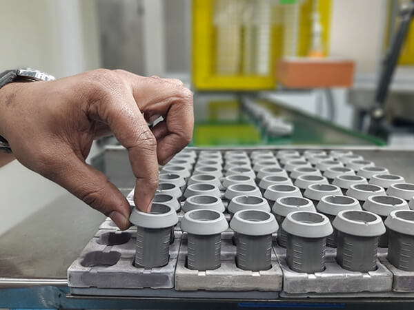
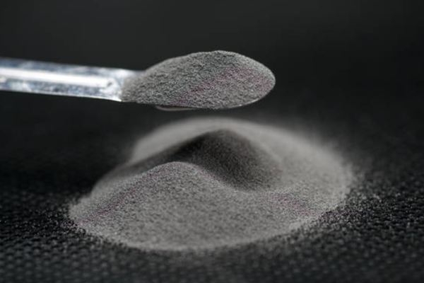
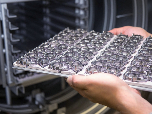
Metal injection molding is suitable when the micro metal part has complex 3D geometry, small bosses, slots, thin ribs, internal features, or production volume that can justify a mold. MIM uses metal powder feedstock, injection molding, debinding, and sintering, so the design must account for shrinkage, support, tooling access, and inspection of small features.
MIM can be a strong candidate for miniature stainless steel components, small lock parts, instrument details, connector elements, and high-volume precision hardware. Buyers should define material grade, critical dimensions, surface finish, strength requirement, and whether any datum surfaces or holes need post-sintering machining.
When do micro stamping and laser cutting fit thin flat parts?
Micro stamping and laser cutting fit thin flat parts when the design is mainly 2D or lightly formed from sheet or foil. Stamping can support repeat production of contacts, clips, terminals, shields, springs, and small brackets when tooling is justified. Laser cutting can support prototype or lower-volume flat profiles, design iteration, and parts where tooling investment is not yet justified.
The RFQ should define burr direction, edge quality, grain direction, flatness, carrier strip needs, bend radius, plating or coating, and handling method. Thin metal parts can deform during blanking, cleaning, packaging, and assembly, so the production route should include how parts will be held and inspected.
When do powder pressing or secondary machining make sense?
Powder pressing can make sense for simple micro metal shapes where the feature layout supports uniaxial compaction and sintering. It is less flexible than MIM for complex undercuts or fine 3D detail, but it may fit simple thin plates, small wear elements, or simple powder metal blanks when the geometry is compatible.
Secondary machining makes sense when only a few features need tighter control than the primary process can provide. For micro metal parts, machining should be limited to critical datum surfaces, precision holes, slots, or mating faces because part handling, fixture design, tool deflection, and burr control can dominate the manufacturing risk.
Which materials should buyers consider for micro metal parts?
Material selection should match strength, corrosion resistance, magnetic behavior, conductivity, wear, and biocompatibility requirements. For MIM, common choices include stainless steel families such as 17-4 PH and 316L when the application needs corrosion resistance or small structural features. For stamping and laser cutting, stainless steel, copper alloy, nickel alloy, and spring steel foils may be considered depending on conductivity, spring behavior, and corrosion needs.
Buyers should provide the required material standard rather than only a trade name when the part is used in a regulated, electrical, or safety-related assembly. Heat treatment, passivation, plating, black oxide, or other finish requirements should be stated with the final performance target.
How do deburring, heat treatment, and finishing affect micro parts?
Deburring, heat treatment, and finishing can change micro part function because the part mass and feature size are small. Tumbling or deburring can remove sharp edges, but it can also round critical features if not controlled. Heat treatment can improve strength or spring behavior, but it can also create distortion if fixturing and process control are not suitable.
Finishing should be defined as part of the manufacturing route. Plating thickness, passivation, black oxide, PVD coating, cleaning, and packaging can affect micro holes, contact areas, spring movement, and assembly fit. Buyers should identify functional surfaces before approving finishing.
What inspection methods control micro metal part risk?
Inspection for micro metal parts should focus on the features that affect assembly function. Useful methods may include optical measurement, microscope inspection, profile projection, CMM for accessible datums, gauge fixtures, burr inspection, flatness checks, coating thickness checks, material verification, hardness checks, and functional assembly trials.
Because micro features are difficult to measure after assembly, buyers should define critical-to-function dimensions on the 2D drawing. A clear inspection plan helps the supplier decide whether tooling, process controls, or secondary operations are needed before quotation.
What RFQ details help choose a micro metal manufacturing process?
The most useful RFQ details are 3D CAD, 2D drawings, thickness target, material grade, annual volume, flatness requirement, burr limit, edge condition, critical dimensions, datum surfaces, surface finish, heat treatment, plating or coating, part handling expectations, packaging requirement, and mating assembly information.
Micro metal process | Where it fits | Main manufacturing risk | RFQ detail to provide |
|---|---|---|---|
Metal injection molding | Complex 3D micro parts with small ribs, bosses, and slots | Sintering shrinkage, tooling access, and feature inspection | Material grade, critical dimensions, annual volume, and post-machining needs |
Sheet metal stamping | High-volume flat or lightly formed contacts, clips, shields, and springs | Burrs, flatness, grain direction, and carrier-strip handling | Sheet grade, thickness, burr side, bend radius, and plating requirement |
Laser cutting | Prototype or lower-volume flat micro profiles | Heat-affected edge, distortion, and edge quality | Profile drawing, edge requirement, flatness, and batch size |
Powder pressing molding | Simple powder metal shapes compatible with pressing direction | Density variation, ejection, and sintering distortion | Pressing direction, material, thickness, and functional surfaces |
Secondary micro-machining | Critical datums, holes, slots, or mating surfaces after primary forming | Fixturing, tool deflection, burrs, and handling damage | Datum scheme, tolerance priority, inspection method, and part holding plan |
Related FAQs
What are the applications of thin-walled MIM part across industries?
What tolerances can precision metal injection molding services typically achieve?
How are tight-tolerance components controlled during the MIM shrinkage process?
Can secondary machining improve tolerances for metal injection molded components?
What quality inspection methods are used for tight-tolerance MIM components?
Can zinc die casting produce thin-wall and complex custom parts?