What Is Parting Line In Aluminum Die Casting Manufacturing?
A parting line in aluminum die casting is the visible boundary where the two die halves meet and separate so the cast aluminum part can be formed and ejected. The practical RFQ problem is deciding where the parting line should sit on a housing, bracket, cover, heat sink, motor component, or structural casting so the die can open while controlling flash, appearance, machining allowance, draft, and inspection risk.
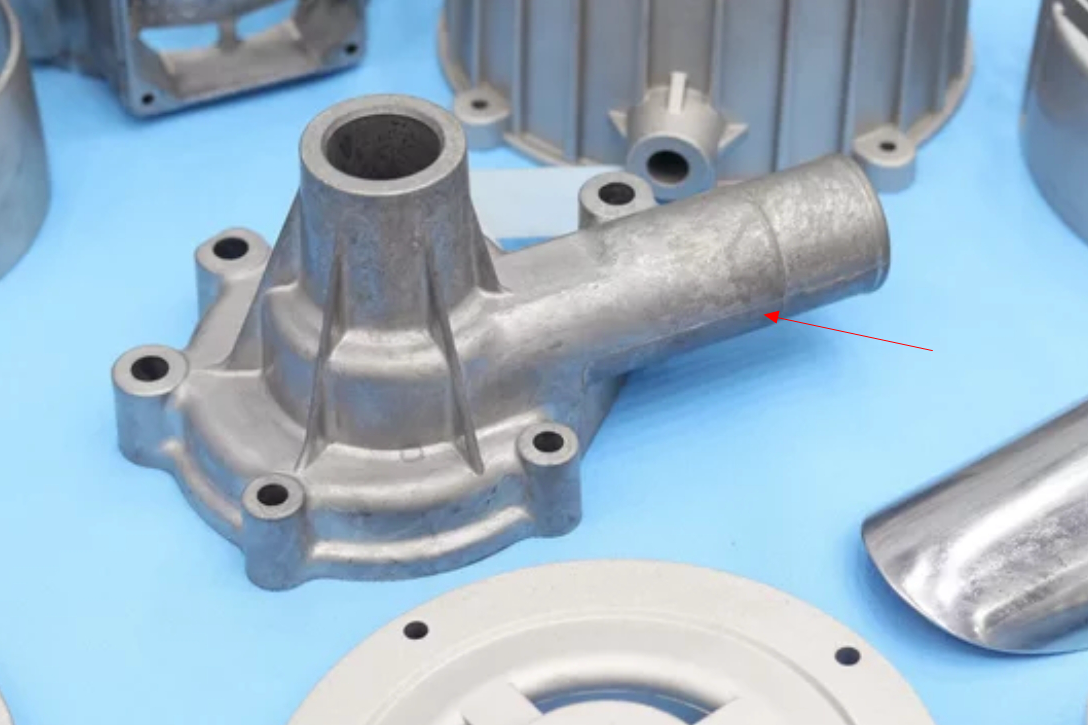
What is a parting line in aluminum die casting?
The parting line is the boundary between the fixed die half and moving die half. During high-pressure aluminum die casting, molten aluminum fills the die cavity. After solidification, the die opens along the parting line so ejector pins and tooling features can release the casting.
The parting line is important because it affects tool design, draft direction, side-action needs, flash trimming, cosmetic appearance, machining stock, dimensional inspection, and casting cost. A poorly placed parting line can create visible marks, extra finishing work, trapped geometry, or difficult ejection.
Parting line decision | Die casting feature affected | RFQ implication for buyers |
|---|---|---|
Parting line location | Visible edge, split surface, and die opening direction | Mark cosmetic surfaces and functional surfaces on the drawing |
Draft direction | Part release from fixed and moving die halves | Confirm which faces can accept draft and which faces need machining |
Flash risk | Thin excess aluminum at die split surfaces | Define flash limits, trimming needs, and protected edges |
Gate and overflow layout | Metal flow, venting, overflow pockets, and trim areas | Share surfaces where gate vestige or overflow marks are unacceptable |
Side-action features | Undercuts, holes, slots, ribs, and internal details | Identify features that cannot move to the main die-open direction |
Machining allowance | Datum surfaces, sealing faces, threaded holes, bearing areas | Separate as-cast surfaces from post-machined surfaces |
Inspection datums | Dimensional measurement and alignment | Define which surfaces control assembly fit and CMM checks |
Why does parting line placement matter for aluminum die cast parts?
Parting line placement matters because the die must open without trapping the casting. If the part geometry creates undercuts, the tool may need slides, lifters, removable inserts, or geometry changes. These tooling decisions affect cost, maintenance, flash control, and production stability.
Parting line placement also affects surface appearance. A parting line on a visible face, customer-facing housing, sealing edge, or precise mounting surface can require trimming, polishing, machining, or redesign. Buyers should identify Class A surfaces, sealing surfaces, and assembly datums before the tool layout is quoted.
For functional castings, the parting line can influence where flash forms and where material is removed after casting. If the flash line crosses a gasket surface, bearing seat, clip interface, or electrical contact area, the casting may require secondary machining or a different parting line strategy.
How does the parting line affect die design and tooling complexity?
The parting line defines how the cavity is split between the two die halves. A simple parting line can make tooling, ejection, trimming, and inspection easier. A complex parting line may be necessary for irregular geometry, but it can increase die construction effort and die maintenance.
Undercuts are a major driver of tooling complexity. Holes, hooks, ribs, slots, and side openings that do not align with the main die opening direction may require side actions. Side actions can be useful, but they add cost and create more areas where flash, wear, or alignment issues can occur.
Buyers should decide whether a feature is functionally required or can be redesigned. Removing or relocating an undercut may reduce tooling complexity without changing the part's core function.
How do parting lines affect flash, trimming, and surface finish?
Flash is the thin excess aluminum that can form at the parting line or around moving tooling interfaces. Flash control depends on die fit, clamping force, metal pressure, parting surface wear, thermal balance, and process maintenance.
Trimming removes gates, runners, overflows, and flash after casting. The RFQ should state which edges can be trimmed normally and which edges need special protection for appearance, sealing, assembly, or safety. If a sharp flash edge is unacceptable, the quote may need deburring, machining, or finishing.
Surface finish expectations should be tied to parting line placement. A visible line on a decorative housing may need different finishing from a hidden line inside a mounting bracket. A machined surface may tolerate a casting line if enough allowance is planned.
How does the parting line affect dimensional inspection and machining?
The parting line can affect dimensional inspection because it may create a small mismatch between die halves or leave flash on a measurement edge. Inspection datums should be chosen on stable functional surfaces rather than on uncontrolled flash or trim areas.
Post-casting machining may be needed for tight bores, threaded holes, sealing faces, bearing seats, flat mounting surfaces, or critical datums. The buyer should identify machined features in the drawing so the supplier can plan casting stock and machining setup.
When a parting line crosses a functional dimension, the buyer and supplier should confirm whether that feature will remain as-cast, be trimmed, be machined, or be moved to another area of the design.
What should buyers provide when parting line placement is important?
A useful aluminum die casting RFQ should include the 3D CAD model, 2D drawing, aluminum alloy, expected volume, functional surfaces, cosmetic surfaces, draft-sensitive features, undercuts, required machining, surface finish, tolerance requirements, assembly interfaces, and inspection datums.
Buyers should also mark areas where parting line marks, flash, ejector marks, gate vestige, or overflow marks are unacceptable. This information helps the supplier evaluate die split, gate location, side-action requirements, trimming, machining, and finishing.
The practical answer is that the parting line is not only a visual line on a casting. The parting line is a tooling decision that affects die opening, surface quality, flash control, secondary operations, dimensional inspection, and total casting cost.
Related FAQs
Which Aluminum Alloys Are Commonly Used for Die Casting Parts?
How Should Buyers Choose Between A380 and ADC12 Aluminum Die Casting?
What Surface Finishes Are Suitable for Aluminum Die Casting Parts?
What Design Factors Affect the Cost of Aluminum Die Casting Parts?
How Can Aluminum Die Casting Defects Be Reduced in Mass Production?
What Types of Aluminum Die Casting Parts Can Neway Manufacture?