How to simulate real EV operating conditions during prototype validation?
To simulate real EV operating conditions during prototype validation, loading must reflect not only peak torque and speed, but also real driving cycles, temperature gradients, vibration, and environmental exposure. Neway combines simulation-driven development with hardware-in-the-loop testing for components used in e-mobility and automotive drivetrains, ensuring that prototypes experience duty cycles similar to those of actual vehicle use from the earliest development stages.
Define Real-World Duty Cycles
The first step is translating drive cycles into component-level loads. Typical urban, highway, and mixed EV drive cycles are converted into torque–speed profiles, regenerative braking events, and start–stop sequences. These inputs define the test matrix for gear sets, motor shafts, differential housings, and inverter enclosures.
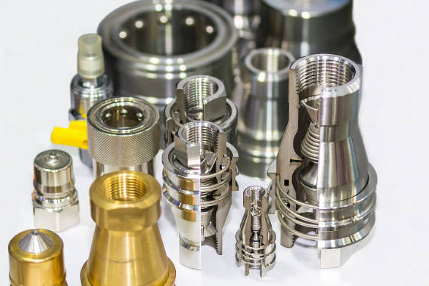
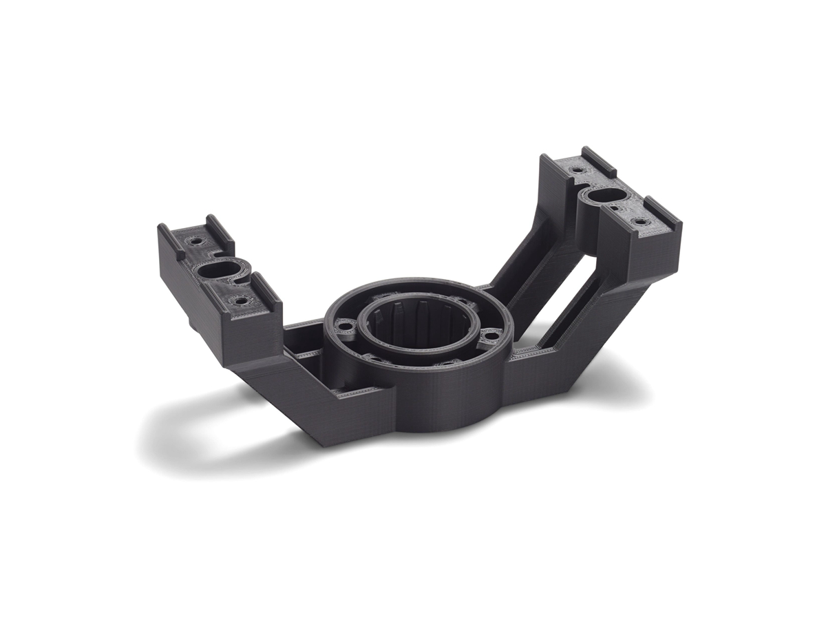
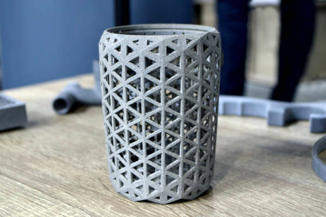
Neway uses early prototypes manufactured via CNC machining prototyping and 3D printing prototyping to quickly evaluate how design changes affect strength, NVH behavior, and efficiency under these mapped duty cycles.
Build Representative Prototypes with Production Intent
To make test results meaningful, prototypes must be as close as possible to production intent in terms of materials and manufacturing routes. Structural housings and motor carriers are produced by processes such as aluminum die casting or precision casting, using alloys like A380 or cast aluminum to capture realistic stiffness and thermal behavior.
Highly loaded small components—spline hubs, locking pawls, and actuator parts—can be produced via metal injection molding in grades such as MIM-4140 or MIM 17-4 PH, ensuring that fatigue performance in test is representative of the eventual series solution.
Combine Mechanical, Thermal, and Electrical Stresses
EV drivetrains operate under tightly coupled mechanical and thermal conditions. Test benches are programmed to apply transient torque and speed profiles while the unit runs at realistic coolant inlet temperatures and flow rates. Cast aluminum inverter housings and e-axle covers produced via prototyping routes are evaluated for hot-spot formation and thermal expansion behavior.
To mirror long-term thermal exposure, materials are conditioned using heat treatment to reach target strength and hardness before testing. Where components are near exhaust paths or high-temperature electronics, thermal coating or thermal barrier coating systems are evaluated to ensure insulation and fatigue resistance under repeated thermal cycling.
Account for Environmental and Road-Load Effects
Real EV conditions include vibration, shock, corrosion, and contamination. Road-load data are translated into multi-axis vibration and shock profiles applied to complete assemblies, including housings, brackets, and electrical connectors. Components for underbody and chassis integration are often built using sheet metal fabrication combined with cast or molded interfaces to replicate real mounting stiffness.
Surface protection is key for accurate lifetime assessment. Coatings such as powder coating, anodizing, or galvanizing are applied before salt-spray and humidity testing so the prototype’s corrosion behavior truly reflects the final product.
Close the Loop Between Simulation and Test
During validation, measured strain, temperature, and vibration data are fed back into digital models to refine load assumptions and safety factors. When deviations are observed, design iterations are implemented and quickly re-tested using rapid molding prototyping or updated CNC prototypes. This closed-loop approach ensures that by the time the drivetrain enters production, it has already endured EV-relevant conditions in both virtual and physical environments.


