Precision Manufacturing for RF & Microwave Components
RF And Microwave Component RFQ Decision: This article explains how buyers can specify metal injection molding, CNC machining prototyping, precision casting, surface finishing, and dimensional inspection for RF connectors, microwave housings, waveguide features, antenna brackets, shielding cavities, and high-frequency structural parts. The practical RFQ problem is deciding which process, conductive material, surface treatment, tolerance evidence, and prototype validation route should be quoted before the buyer performs RF testing and system-level approval.
RF and microwave components connect mechanical geometry to electrical behavior. A connector shell, waveguide cavity, antenna mount, shielding cover, and microwave housing may all need precision metal manufacturing, but each part controls a different risk: resonance, impedance path, grounding, thermal path, assembly repeatability, or dimensional stability. Buyers should state the RF function in the RFQ so manufacturing can protect the features that the buyer will later verify through electrical testing.
Which RF Component Feature Controls The Manufacturing Route?
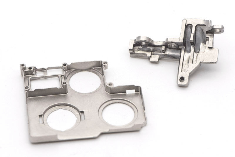
The manufacturing route should be selected from the feature that controls RF function. Waveguide cavities and microwave housings often need machined datums, surface finish control, and stable cavity geometry. RF connectors may need small metal features, conductive surfaces, threads, spring interfaces, and plating or passivation. Antenna brackets and shielding parts may need precise mounting holes, grounding surfaces, and repeatable assembly geometry.
MIM can be useful for small complex connector parts, shield features, and repeatable metal geometries when production volume can support tooling. CNC machining prototyping is useful when the buyer needs early RF fit, cavity geometry, or interface validation before production tooling. Precision casting can be reviewed for selected housings or structural metal parts where casting geometry reduces machining burden.
RF Or Microwave Part Type | Process Route To Review | RFQ Risk To Clarify | Inspection Evidence |
|---|---|---|---|
RF connector shell or pin carrier | MIM plus secondary machining | Thread fit, conductive surface, small feature repeatability | CMM report and surface treatment record |
Waveguide cavity or microwave housing | CNC machining prototype or precision machining | Cavity geometry, surface finish, datum stability | Dimensional report and surface finish inspection |
Antenna bracket or shield cover | Precision casting, machining, or formed metal route | Mounting hole position, flatness, grounding area | First article report and fit check |
Thermal or structural RF support | CNC machining or precision casting | Heat path, weight, material conductivity | Material record and critical dimension inspection |
When Should Buyers Use MIM For RF Connector Parts?
MIM should be considered when an RF connector or microwave component has small metal geometry, repeated production demand, and features that are difficult to machine efficiently. Connector shells, locking features, small brackets, shielding elements, and internal metal features can be candidates when the drawing allows MIM shrinkage planning and secondary machining where needed.
The RFQ should identify conductive surfaces, threaded features, mating datums, plating zones, and dimensions that control assembly fit. Buyers should ask whether secondary machining is needed for threads, sealing faces, or reference datums. If the part is still changing, CNC machining prototyping can provide early geometry before MIM tooling. If the part geometry is stable, the RFQ can compare MIM, CNC machining, and precision casting using the same acceptance features.
Which Materials And Surface Treatments Affect RF Manufacturing?
Material and surface finish should be specified together because RF parts often rely on conductivity, corrosion resistance, thermal behavior, and surface condition. Aluminum alloys, copper alloys, stainless steels, and selected MIM materials create different tradeoffs for conductivity, machining, mass, plating, and corrosion resistance. The buyer should define whether the part needs low electrical resistance, corrosion protection, wear resistance, or a controlled surface finish for the RF path.
Surface treatment references such as electroplating, passivation, and as-machined surface finishes can support RFQ discussion. The RFQ should identify mask areas, mating surfaces, grounding zones, and any surface where coating thickness changes electrical or mechanical fit.
How Should RF Cavity And Waveguide Dimensions Be Controlled?
RF cavity and waveguide dimensions should be controlled through datum planning, machining sequence, inspection access, and surface finish notes. Buyers should identify the features that control resonance, shielding, grounding, alignment, and assembly. If a cavity feature cannot be easily inspected after machining or casting, the RFQ should define the inspection approach before quotation.
CNC machining can support prototype cavities, waveguide features, and test housings where the buyer needs quick iteration. MIM or casting routes may need secondary machining on functional surfaces. CMM dimensional inspection can support datums and critical interfaces, while optical comparator inspection can support profile checks on smaller features.
What Prototype Evidence Should Buyers Request Before Production?
Prototype evidence should match the question the buyer wants to answer. A visual prototype may support packaging or assembly review. A functional RF prototype may need representative material, surface finish, cavity geometry, and connector interfaces. A production-intent prototype may need the same datum scheme and inspection evidence expected from later production.
The RFQ should state whether prototype parts will be used for RF testing, thermal testing, fit check, or supplier process review. Buyers should request dimensional reports for cavity features, connector datums, threaded interfaces, grounding surfaces, and mounting holes. Manufacturing evidence does not replace RF system testing, but it helps the buyer connect RF test results to controlled physical features.
RFQ Requirement | Specific Manufacturing Detail | Buyer Decision Supported |
|---|---|---|
RF cavity geometry | Datum surfaces, cavity depth, wall finish, inspection access | Prototype RF test and production route selection |
Connector interface | Thread, pin location, mating face, plating zone | Assembly fit and signal path review |
Shielding feature | Grounding surface, flatness, contact edge, material | EMI shielding and mechanical release review |
Thermal path | Material conductivity, heat spreader surface, weight target | Heat management and material comparison |
What Should Buyers Include In An RF Component RFQ?
An RF component RFQ should include 3D CAD, 2D drawings, RF function, target process, material grade, surface treatment, critical dimensions, cavity or waveguide features, connector interfaces, grounding surfaces, inspection reports, prototype purpose, and production stage. For MIM connector parts, buyers should identify shrinkage-sensitive dimensions, secondary machining needs, and coating zones. For CNC-machined RF housings, buyers should identify datums, surface finish, cavity geometry, and threaded interfaces.
Important decisions should be stated directly. If the part is an RF cavity, specify cavity geometry and surface condition before asking for price. If the part is a connector, specify mating datums and conductive surface treatment. If the part is a prototype, specify whether the buyer will use it for RF measurement, mechanical fit, thermal testing, or production route review.
Related FAQs
How should RF cavity geometry and shielding be controlled for resonance?
Which surface treatments support long-term stability for RF connectors?
How should buyers balance conductivity, heat, weight, and cost when selecting RF materials?
What steps take RF components from prototype to full-scale production?
Which materials are best suited for CNC machining in critical applications?
What inspection methods are used for tight-tolerance MIM components?