Can rapid molding produce parts with complex geometries?
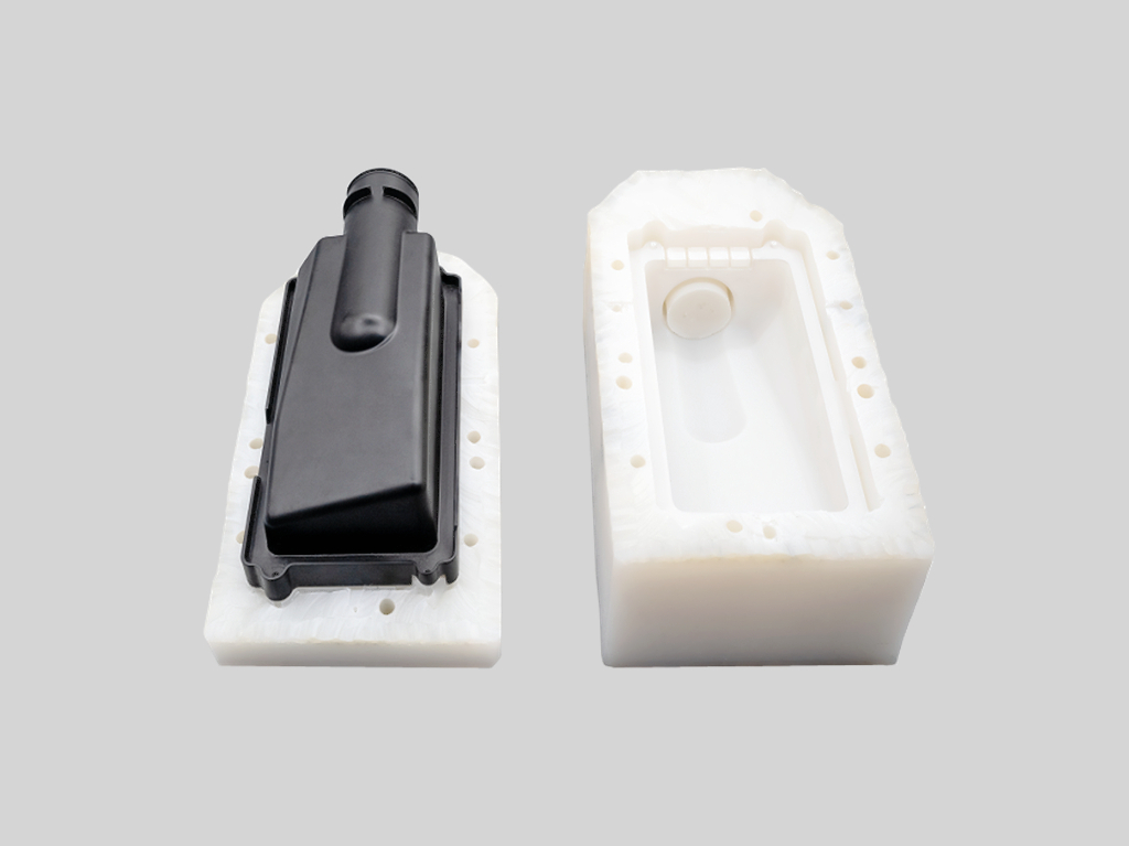
Rapid molding can produce some complex geometries when the part design is reviewed for mold flow, draft, wall thickness, undercuts, side actions, inserts, parting lines, ejection, and surface finish. This FAQ helps buyers evaluate complex molded housings, clips, brackets, covers, snap-fit parts, enclosures, connector bodies, and functional prototypes when an RFQ must balance design freedom with rapid tooling feasibility.
Can rapid molding produce parts with complex geometries?
Rapid molding prototyping can produce complex parts when the geometry is designed for moldability. Features such as ribs, bosses, clips, snap fits, holes, textures, inserts, and some undercuts may be possible, but every feature must be reviewed against tool access, material flow, cooling, ejection, and inspection.
The buyer should not assume that a 3D printed or CNC machined shape can be molded without changes. Rapid molding follows injection molding rules, so design-for-manufacturing review is essential before quoting tooling and lead time.
Complex feature | Rapid molding feasibility issue | Possible design response | RFQ detail to provide |
|---|---|---|---|
Undercuts | Can prevent straight mold opening and part ejection | Use side actions, hand-loaded inserts, redesign, or split the feature | Undercut function, allowed witness marks, and production quantity |
Thin walls | Can cause short shots, weak areas, sink imbalance, or flow hesitation | Adjust wall thickness, gate location, resin choice, or rib structure | Wall thickness map, resin, flow length, and strength requirement |
Thick sections | Can create sink marks, voids, long cooling time, and dimensional variation | Core out thick zones, add ribs, or redesign bosses | Cosmetic surfaces, functional load, and allowable design changes |
Snap fits and clips | Need correct material, flex direction, draft, and ejection support | Review resin, radius, draft, and stress concentration | Assembly force, cycle life expectation, and mating-part data |
Textures and cosmetic faces | Can require draft, polish control, texture direction, and careful gate placement | Define texture zones, gate marks, parting line, and visible surfaces | Cosmetic side, texture standard, color, and acceptance criteria |
Insert features | May add loading steps, tolerance stack-up, and molding risk around inserts | Design insert retention, loading access, and inspection method | Insert material, insert drawing, pull-out requirement, and quantity |
Which complex features are often possible in rapid molding?
Ribs, bosses, screw posts, snap fits, clips, holes, windows, textures, living-hinge-like features in suitable materials, and selected undercuts may be possible when the design follows molding rules. The feasibility depends on resin flow, draft, tool access, cooling, and ejection.
Buyers should identify which complex features are functional and which are cosmetic. Functional clips, sealing surfaces, and assembly datums deserve more review than decorative shapes.
How do undercuts, side actions, and inserts affect rapid tooling?
Undercuts, side actions, and inserts can make rapid tooling more complex because the mold cannot open and eject the part with only a simple straight pull. Side actions, hand-loaded inserts, collapsible concepts, or part redesign may be needed.
These features can affect cost, lead time, repeatability, and tool maintenance. The RFQ should define the undercut purpose and whether a design change is acceptable before the tool route is selected.
How do wall thickness, ribs, and bosses affect complex molded parts?
Wall thickness, ribs, and bosses control material flow, strength, sink marks, warpage, and cooling. Thin walls may be hard to fill, while thick sections may create sink or void risk. Ribs and bosses can improve stiffness but need correct thickness, radius, draft, and spacing.
Buyers should provide a 3D model and allow DFM feedback on wall transitions. Small geometry changes before tooling can prevent expensive mold changes after trial molding.
How do material and surface finish change complex geometry feasibility?
Material choice affects complex geometry because flow, shrinkage, flexibility, heat resistance, and tool wear differ by resin. ABS, PC, PP, POM, TPU, filled grades, and high-temperature materials do not fill, cool, or eject the same way.
Surface finish also matters. High-gloss faces, textured surfaces, transparent parts, and painted parts require gate, parting line, and ejection planning. Buyers should mark cosmetic surfaces clearly on the drawing.
When should buyers use another process before rapid molding?
Another process may be better when the design is still changing heavily, the geometry violates basic molding rules, the quantity is very small, or the buyer only needs fit-check geometry. 3D printing or CNC machining may be faster for early validation before converting the design to a molded part.
Rapid molding becomes more useful when the buyer needs molded material behavior, surface finish, snap-fit testing, assembly trials, or low-volume production from a design that is ready for DFM review.
What RFQ information helps confirm complex rapid molding feasibility?
A useful RFQ includes 3D model, 2D drawing, target resin, wall thickness, draft, undercuts, parting-line preferences, cosmetic surfaces, inserts, snap-fit requirements, tolerance, quantity, surface finish, and whether design changes are allowed after DFM review.
With those details, the supplier can recommend rapid molding, design changes, side actions, inserts, production tooling, CNC machining, 3D printing, or another process. Complex geometry is feasible only when the tooling route and part function are reviewed together.
Related FAQs
What design features should be avoided in rapid injection molding?
What are the typical tolerances achievable in rapid injection molding?
What materials are commonly used in rapid molding processes?
What is rapid molding and how does it differ from traditional molding processes?
How quickly can parts be produced using rapid molding techniques?
What are the cost benefits of rapid molding compared to traditional methods?