What Are the Types of Milling Operations: A Comprehensive Guide
CNC Milling Operations RFQ Decision: CNC milling operations use computer-controlled rotary cutting tools to remove material from a workpiece and produce machined plates, housings, brackets, pockets, slots, bosses, holes, threads, contours, and precision prototypes. This article explains how buyers should choose face milling, end milling, slot milling, side milling, profile milling, pocket milling, thread milling, gear milling, and multi-axis milling based on part geometry, material, tolerance requirements, surface finish, production volume, and inspection evidence. The practical RFQ problem is selecting the milling operation route that can make the required features without adding avoidable setup, tool access, burr, distortion, or inspection risk.
CNC milling operation selection starts from the drawing. A supplier needs the 2D drawing, 3D CAD model, material grade, datum scheme, critical dimensions, surface finish requirement, threaded features, deburring requirement, and expected quantity. Those details help the supplier decide whether a feature should be face milled, end milled, slot milled, drilled, thread milled, contoured, or moved to a multi-axis setup.
How Does CNC Milling Create Machined Part Features?
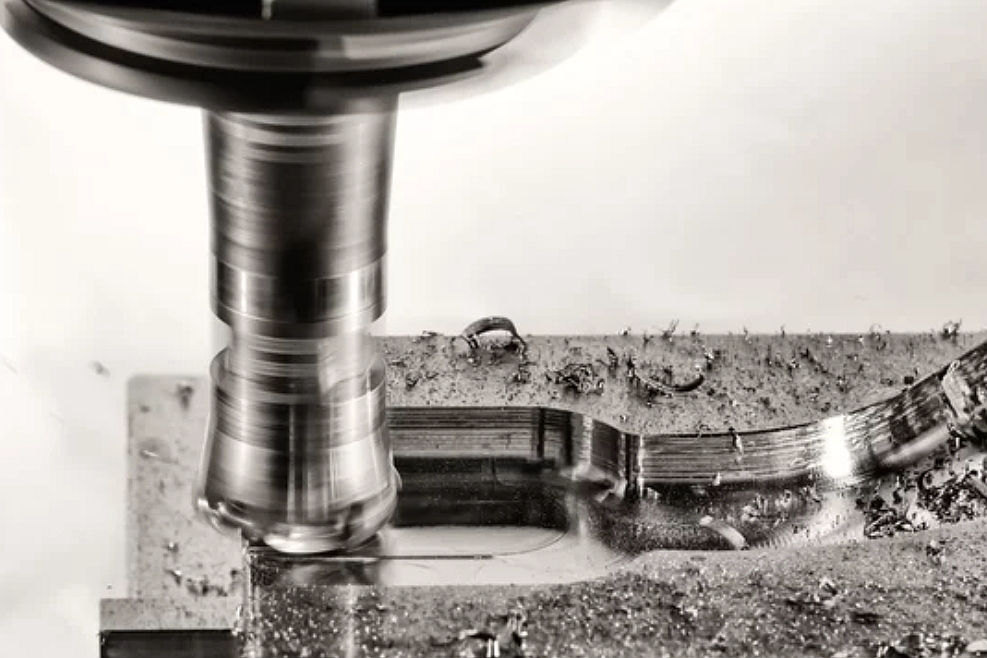
CNC machining prototyping uses programmed toolpaths, cutting tools, fixtures, and machine axes to remove material from a workpiece. In CNC milling, the rotating tool cuts while the machine controls tool position, feed, spindle speed, depth of cut, and tool engagement. The operation route depends on feature orientation and tool access.
The buyer question is not only whether the part can be milled. The buyer should ask which features drive setup count, tool reach, surface finish, and inspection complexity. A flat mounting face, a deep pocket, a thin wall, a slot, and a side hole may require different milling strategies even when those features are on the same part.
Which Milling Operations Match Common Part Features?
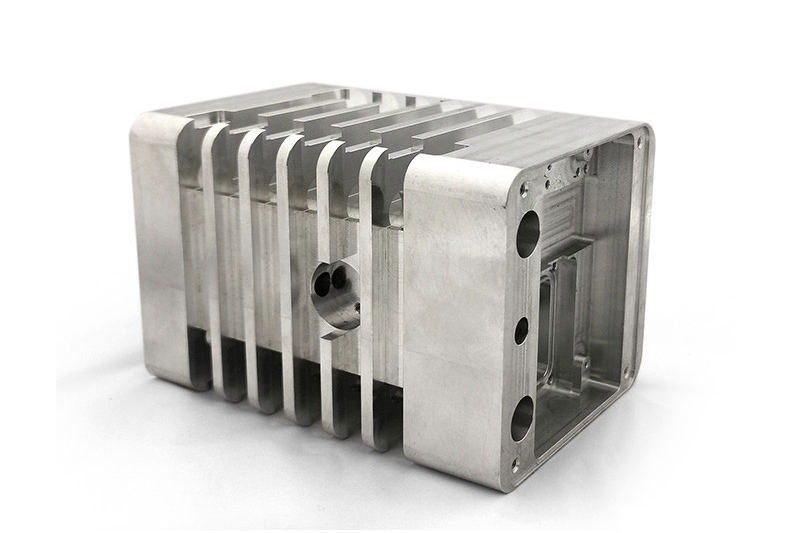
Face milling is typically used to create flat surfaces and datum faces. End milling can produce pockets, slots, contours, shoulders, and side walls. Slot milling cuts channels and grooves. Side milling machines side features and edges. Profile milling follows outside or inside contours. Pocket milling removes material inside a bounded area. Thread milling creates internal or external threads when the part geometry and thread requirement support that route.
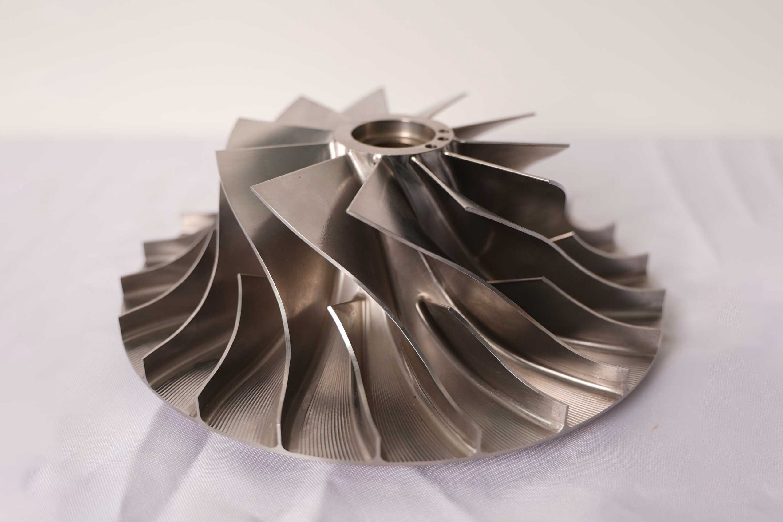
Gear milling, form milling, angle milling, and saw milling are more specialized operations. These operations should be reviewed when the drawing includes gear teeth, shaped contours, angled surfaces, or narrow saw-cut features. When features sit on multiple sides of the part or require difficult tool angles, multi-axis milling may reduce refixturing or improve tool access.
How Do Material, Geometry, and Tool Access Affect Milling Operation Selection?
Material affects cutting force, tool wear, heat, burr formation, and surface finish. Aluminum, stainless steel, titanium, copper alloys, engineering plastics, and other materials may require different cutting tools, coolant strategies, feeds, speeds, and workholding. The RFQ should identify the material grade, heat treatment if applicable, and any material certificate requirement.
Geometry affects tool access and setup planning. Deep pockets, thin walls, undercuts, small radii, long slots, tall ribs, and hard-to-reach side features can create tool deflection, chatter, burrs, or poor surface finish. The buyer should mark critical features and clarify whether corner radii, pocket floors, and thin walls are functional or cosmetic.
How Do Tolerance, Surface Finish, and Deburring Requirements Change Milling Choices?
Tolerance and surface finish requirements should be tied to part function. A sealing face, bearing seat, dowel hole, and threaded mounting feature may need different process control than a clearance pocket or hidden relief cut. CNC milling can support many precision features, but the RFQ must state datum references, inspection method, and acceptance criteria.
Deburring is part of the milling route, not an afterthought. Slots, cross holes, pocket edges, thin walls, and intersecting features can create burr risk. Buyers should identify burr-sensitive edges, cosmetic edges, and functional edges. Secondary finishing, polishing, anodizing, passivation, plating, or heat treatment should also be listed because these operations can affect final dimensions and surfaces.
When Should Buyers Use CNC Milling for Prototypes or Production Parts?
CNC milling is often suitable for functional prototypes, bridge production, tooling components, fixtures, and production machined parts when the geometry, material, tolerance, and quantity match the route. For prototypes, CNC milling can provide production-intent material and machined surfaces. For production, the supplier should review cycle time, fixture strategy, tool life, inspection plan, and repeatability.
The RFQ should state whether the project is a prototype, validation build, or production order. A prototype may prioritize quick design feedback and functional testing. A production part may need fixture planning, in-process checks, batch traceability, consistent deburring, and packaging controls. The milling operation route should match that production stage.
CNC Milling Operation | Machined Feature | RFQ Detail Needed | Manufacturing Risk to Review |
|---|---|---|---|
Face milling | Flat datum faces, mounting faces, and broad surfaces. | Surface finish, flatness need, datum role, and material grade. | Tool marks, flatness variation, workholding distortion, and inspection setup. |
End milling and pocket milling | Pockets, slots, shoulders, ribs, bosses, and contoured walls. | Pocket depth, corner radius, wall thickness, bottom finish, and critical edges. | Tool deflection, chatter, burrs, sharp internal corner requests, and thin-wall movement. |
Thread milling | Threaded holes or external thread features. | Thread standard, depth, access direction, gauge requirement, and mating hardware. | Thread fit, burrs at thread entry, tool access, and inspection method. |
Profile or multi-axis milling | Complex contours, angled faces, undercuts, and features on multiple sides. | 3D CAD model, datum scheme, setup faces, visible surfaces, and tolerance priorities. | Setup stack-up, tool reach, surface mismatch, part collision, and inspection planning. |
What Neway Precision Reviews for CNC Milling Operation Selection
Neway Precision reviews CNC milling RFQs by checking material grade, part geometry, datum scheme, workholding, tool access, setup count, feature orientation, wall thickness, hole depth, thread requirements, surface finish, burr control, secondary operations, and inspection documents. The review connects the milling operation route with material behavior, machine capability, tooling, fixture design, and buyer acceptance criteria.
A complete RFQ should include the 2D drawing, 3D CAD model, material grade, heat treatment if applicable, surface finish requirement, critical dimensions, datum references, threaded features, cosmetic surfaces, burr-sensitive edges, expected quantity, secondary operations, and requested inspection report. Clear RFQ data helps determine whether the part should use standard 3-axis milling, multi-axis milling, turning plus milling, or another machining route.
Related FAQs