Precision Electrical & Connector Solutions for Lighting
Lighting Electrical Connector RFQ Decision: This article explains how buyers can specify plastic injection molding, insert molding, metal injection molding, and CNC machining prototyping for LED connectors, terminal housings, sockets, driver connector parts, waterproof cable interfaces, insert-molded contacts, and small metal connector features. The practical RFQ problem is deciding which insulation material, metal insert, contact geometry, waterproof design, surface finish, and validation evidence should be quoted before the buyer confirms electrical performance and regional compliance.
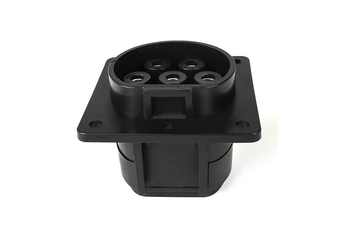
Lighting connector components combine plastic insulation, metal conductivity, mechanical locking, sealing, and repeated mating behavior. A terminal block, LED driver connector, outdoor cable gland, insert-molded contact carrier, and small metal latch each has different manufacturing risks. Buyers should state the electrical function and environmental exposure in the RFQ so the supplier can quote molding, insert handling, metal part production, and inspection evidence correctly.
Which Lighting Connector Part Type Is Being Quoted?
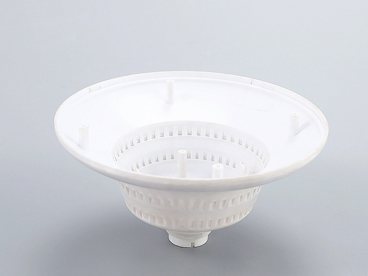
The part type should control the manufacturing route. Plastic injection molding can fit connector housings, terminal blocks, wire guides, latch covers, and insulation bodies. Insert molding can combine metal pins, terminals, busbars, threaded inserts, and plastic insulation in one molded component. MIM can support small metal connector features, locking elements, contact supports, and compact mechanical parts. CNC machining prototyping can support early connector samples and metal contact fixtures before tooling.
The RFQ should identify whether the component carries current, insulates a conductor, seals an outdoor interface, locks a cable, guides a wire, or provides a mechanical contact surface. This decision affects resin choice, insert material, molding tolerance, plating or surface treatment, and inspection requirements.
Lighting Connector Component | Process Route To Review | RFQ Risk To Clarify | Inspection Evidence |
|---|---|---|---|
Plastic connector housing | Plastic injection molding | Insulation, latch geometry, material heat exposure | Dimensional report and material confirmation |
Insert-molded terminal carrier | Insert molding | Insert position, plastic-metal bonding, flash control | Insert location inspection and pull or fit review when required |
Small metal latch or contact support | MIM or CNC machining prototype | Small feature tolerance, wear surface, secondary machining | CMM report and surface treatment record |
Outdoor waterproof connector interface | Injection molding plus seal design | Gasket seat, cable exit, waterproof rating requirement | Dimensional inspection and buyer-defined sealing test support |
When Should Buyers Use Insert Molding For Lighting Connectors?
Insert molding should be considered when the connector needs metal terminals, pins, busbars, threaded inserts, or contact features fixed inside a molded plastic body. Insert molding can reduce separate assembly steps, but the RFQ must control insert placement, plastic flow around the metal, flash risk, material compatibility, and inspection access.
Buyers should provide insert drawings, terminal material, plating or surface treatment, plastic resin candidate, mold orientation concerns, and critical insert position tolerances. The insert molding process article and insert molding service page are useful references when the buyer is comparing insert molding with separate assembly or overmolding.
Which Materials Affect Contact Resistance And Insulation?
Material selection should separate the conductor, the insert, and the insulation body. Copper alloys, stainless steels, plated contacts, or other approved metal inserts may be considered for contact features depending on current, spring behavior, corrosion exposure, and wear. Engineering plastics may be considered for insulation depending on heat exposure, flame requirement, dimensional stability, and outdoor conditions.
The RFQ should avoid broad wording such as "good electrical material" without contact geometry or current requirement. Buyers should state current range, mating cycle expectation, contact surface, plating or coating requirement, insulation material preference, and regional electrical requirements. Manufacturing evidence can support material and dimensional records; the buyer's electrical test confirms contact resistance and compliance.
How Should Waterproof And Outdoor Lighting Connector Requirements Be Defined?
Waterproof connector requirements should be defined through sealing geometry, cable exit design, gasket seat, plastic material, insert exposure, and test requirement. Outdoor lighting connectors may face rain, UV exposure, temperature cycling, dust, vibration, and repeated installation. The RFQ should state the required waterproof rating or test method if the buyer has one, but the drawing should still identify the physical sealing surfaces that manufacturing must control.
Plastic housing references such as plastic housing waterproof protection, UV and corrosion resistant materials and finishes, and plastic enclosure EMI shielding can support design review. Final environmental and electrical approval should follow the buyer's lighting system validation.
What Inspection Evidence Should Connector Buyers Request?
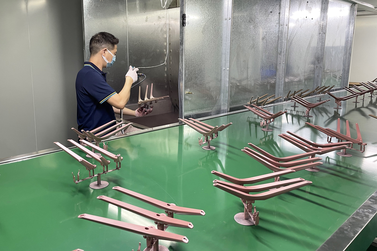
Inspection evidence should focus on the features that affect electrical connection, sealing, assembly, and repeated mating. CMM or fixture inspection can support insert position, terminal spacing, latch geometry, cable exit features, and mounting datums. Surface treatment records can support plated or passivated contact features. Visual inspection can support flash, short shots, sink marks, exposed insert areas, and sealing surface defects.
The RFQ should define whether evidence is required for prototypes, first article samples, validation lots, or production shipments. CMM dimensional inspection can support connector datums and insert positions. Prototype samples should be tied to a clear buyer question such as contact fit, waterproof design, mating cycle review, or production tooling approval.
RFQ Requirement | Specific Manufacturing Entity | Buyer Decision Supported |
|---|---|---|
Metal insert | Terminal alloy, plating zone, insert position, burr direction | Contact resistance and molding feasibility review |
Plastic insulation body | Resin grade, wall thickness, latch geometry, heat exposure | Material selection and tooling review |
Waterproof interface | Gasket seat, cable exit, seal surface, test requirement | Outdoor lighting connector validation |
Prototype stage | CNC contact sample, molded trial part, first article | Fit check, electrical test, and production approval planning |
What Should Buyers Include In A Lighting Connector RFQ?
A useful lighting connector RFQ includes CAD files, 2D drawings, connector function, current requirement, voltage or insulation requirement when available, metal insert drawing, plastic resin candidate, plating or surface treatment, waterproof rating or test method, mating cycle expectation, cable exit geometry, latch details, prototype purpose, production stage, and inspection report requirements. For insert molding, buyers should include insert placement tolerances and exposed metal areas. For plastic connector housings, buyers should identify sealing surfaces, latch features, cosmetic surfaces, and material requirements.
Important decisions should be stated directly. If the connector is used outdoors, specify waterproof and UV exposure requirements first. If contact resistance is the main risk, specify contact material, plating zone, and mating cycle requirement. If tooling risk is the main issue, request CNC or molded prototypes before releasing production tooling.
Related FAQs
What waterproof ratings must outdoor lighting connectors meet and how are they achieved?
What material and design factors matter for high-current LED driver connections?
How can buyers maintain stable contact resistance after repeated connector mating cycles?
What regional electrical safety standards should lighting connector buyers review?
What is the typical development timeline for custom lighting connectors?
What is the difference between insert molding and overmolding?