What Is the Sand Core of Sand Casting
What is a sand core in sand casting?
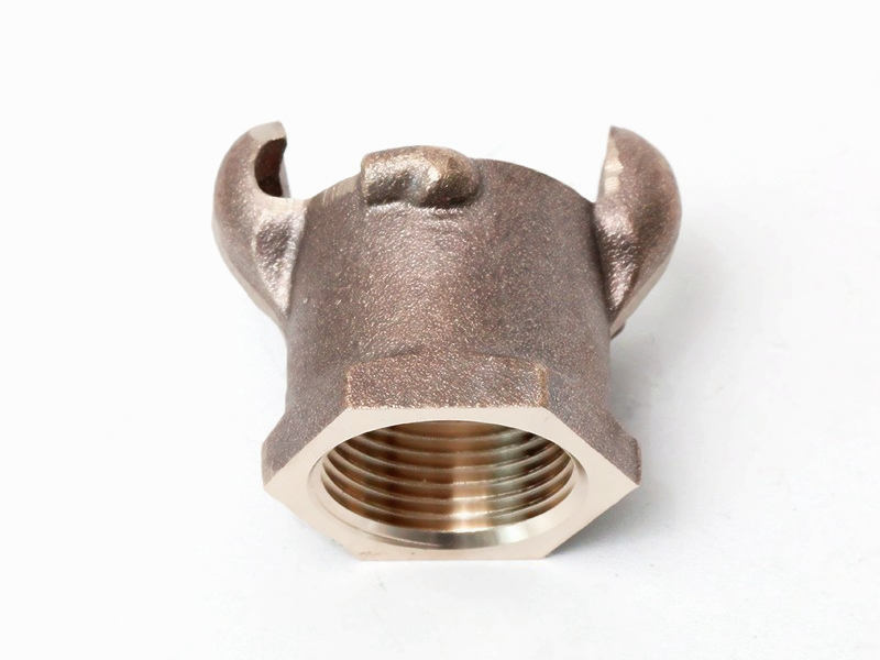
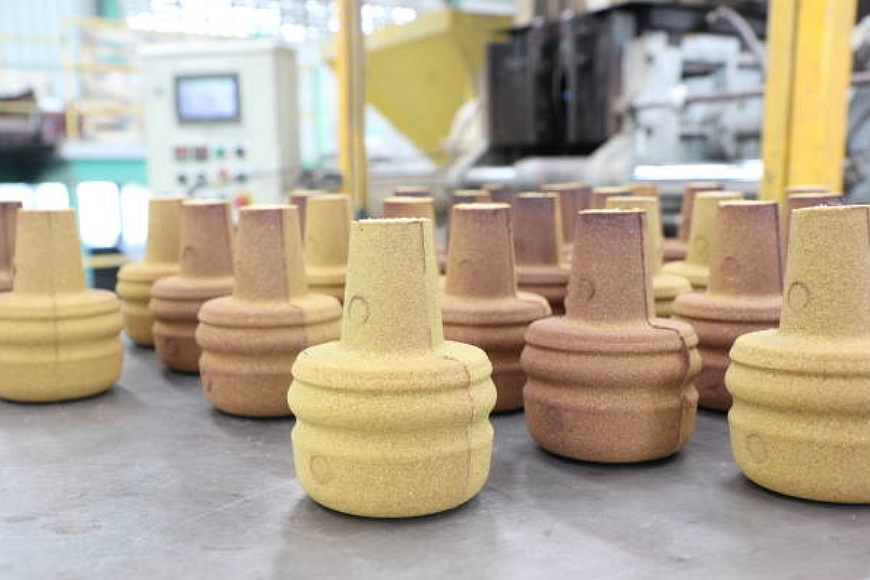
A sand core is a shaped body of bonded sand placed inside a mold cavity to form internal holes, hollow sections, passages, undercuts, or recessed features in sand casting. Sand core design should connect internal passage geometry, core print support, core strength, permeability, collapsibility, gas venting, machining allowance, and inspection evidence. The practical RFQ problem is deciding whether the required internal feature can be cast with a stable removable core or should be redesigned, machined, or made by another process.
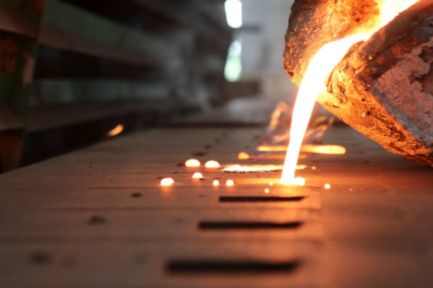
When molten metal fills the mold, the sand core occupies the space that should remain hollow. After solidification, the core is removed by shakeout, mechanical cleaning, water-assisted removal, or other approved cleaning methods depending on the binder and casting geometry.
How do sand cores create internal passages?
The mold cavity defines the outside shape of the casting, while the sand core defines the internal negative space. Core prints, chaplets when required, and mold features hold the core in position during mold assembly and metal pouring.
Core location is critical. If a core shifts, floats, breaks, or vents poorly, the casting can have wall-thickness variation, blocked passages, gas defects, inclusions, or machining stock problems. Drawings should show core-driven features, cleanup openings, and inspection access wherever possible.
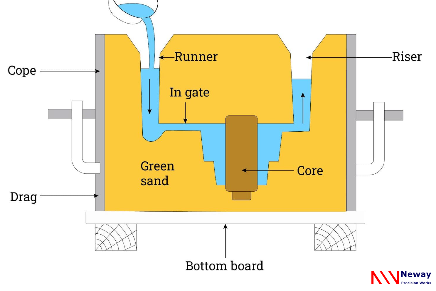
What core properties matter for cast metal parts?
A useful sand core needs enough strength to survive handling, mold assembly, and metal pouring. A sand core also needs permeability so gases can escape, dimensional stability so internal features stay in position, and collapsibility so the core can be removed after the casting solidifies.
Other properties can matter depending on the alloy and part. Binder type, sand grain size, coating, venting method, moisture control, storage condition, and thermal behavior can affect gas defects, surface finish, core erosion, and cleaning difficulty.
How are sand cores manufactured?
Sand cores may be produced with cold box, hot box, shell core, no-bake, or other core-making processes depending on the part size, production quantity, core strength, dimensional control, and binder requirements. The core-making route should fit the casting alloy, core geometry, venting needs, and removal method.
Core boxes define the core shape. After forming and curing, the core may be coated, dried, inspected, and stored before mold assembly. For complex castings, multiple cores may be assembled into a core package to form internal geometry.
What design risks cause core-related casting defects?
Core-related defects can include core shift, core breakage, gas porosity, veining, metal penetration, sand inclusion, blocked internal passages, rough internal surfaces, and poor wall-thickness control. These problems often come from inadequate core support, poor venting, excessive metal pressure, insufficient core strength, difficult cleaning access, or unclear drawing requirements.
The buyer should identify internal passages, pressure zones, sealing features, cooling channels, oil passages, bolt bosses, and machining datums. If the internal geometry must be verified, the RFQ should state whether sectioning, borescope inspection, pressure test, leak test, X-ray inspection, CT inspection, or other evidence is required.
How are sand cores removed and inspected?
Core removal must be planned before casting. A hollow casting needs openings or access paths that allow core sand to be removed without damaging the part. Deep blind cavities, narrow channels, and trapped pockets can make cleaning difficult.
Inspection after core removal may include visual inspection, dimensional checks, CMM inspection, borescope inspection, pressure testing, leak testing, sectioning, X-ray inspection, or CT inspection. The required evidence depends on whether the cored feature is cosmetic, functional, pressure-related, or safety-related.
Core Design Factor | Why It Matters | Casting Risk to Check | RFQ Information Needed |
Core print support | Holds the core in position during mold assembly and pouring | Core shift, wall-thickness variation, blocked passages, and machining stock error | Core print locations, datum scheme, internal cavity drawing, and machining allowance |
Core strength | Allows the core to survive handling, assembly, and molten metal pressure | Core breakage, sand inclusions, rough internal surfaces, and scrap | Core geometry, alloy, pour temperature, wall sections, and handling limits |
Permeability and venting | Allows gases from the core and mold to escape during pouring | Gas porosity, blowholes, surface defects, and internal defects | Venting path, binder type, core coating, pressure requirement, and inspection method |
Collapsibility and removal | Allows core sand to be removed after solidification | Trapped sand, blocked channels, cleaning damage, and functional failure | Cleaning openings, internal passage size, removal method, and acceptance criteria |
Inspection access | Confirms that internal features meet functional requirements | Undetected blockage, leakage, dimensional error, and hidden defects | Borescope, leak test, pressure test, X-ray, CT, sectioning, or report requirements |
What should buyers provide for a cored sand casting RFQ?
A useful RFQ should include the 2D drawing, 3D model, alloy grade, quantity, internal passage geometry, core print details if available, wall-thickness requirements, machining allowance, cleaning openings, pressure or leak requirements, surface finish, heat treatment, and inspection method.
If a cored feature is critical, the buyer should mark the internal feature as functional on the drawing. That helps the foundry review core design, mold assembly, cleaning access, machining plan, and inspection evidence before quotation.
Related FAQs