Common Defects and Solutions in aluminum die casting
Which aluminum die casting defects matter in RFQ review?
Aluminum die casting defects can affect housings, covers, brackets, heat-dissipation parts, frames, and pressure-containing components. Aluminum die casting defect review should connect each defect to the part feature, functional risk, process cause, and inspection evidence. The practical RFQ problem is deciding which defects are cosmetic, which defects affect machining or assembly, and which defects require inspection such as CMM measurement, visual standard, X-ray inspection, CT inspection, leak testing, or pressure testing.
Common aluminum die casting defects include gas porosity, shrinkage porosity, cold shuts, misruns, flash, parting-line mismatch, hot cracks, surface defects, and machining exposure of internal voids. Most defect controls start before tooling: alloy selection, wall balance, gate and runner design, venting, overflow location, die temperature, cooling layout, clamping control, and machining allowance all influence final part quality.
How does porosity affect aluminum die cast parts?
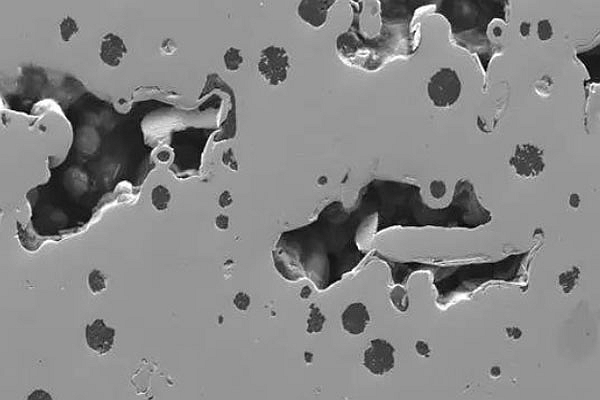
Porosity is a void or pore inside an aluminum die cast part, and it becomes important when the void affects strength, leak performance, pressure tightness, cosmetic surfaces, or machined features. Gas porosity can come from air entrapment, poor venting, turbulent filling, moisture, dissolved gas, or unsuitable gate and runner design.
Porosity control starts with metal flow and air evacuation. The RFQ should identify pressure surfaces, sealing faces, machined bores, leak paths, and cosmetic areas because different areas can require different acceptance criteria. Inspection may include sectioning, X-ray inspection, CT inspection, leak testing, or pressure testing when the part function requires internal-defect review.
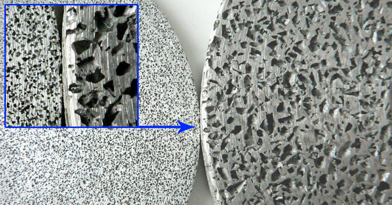
How do shrinkage and microporosity form in die cast sections?
Shrinkage and microporosity form when aluminum contracts during solidification and the local metal supply cannot compensate for volume change. Thick sections, uneven wall transitions, isolated bosses, heavy ribs, poor cooling balance, and unsuitable feeding conditions can increase shrinkage risk.
The solution direction is not only changing one machine setting. The part design may need wall-thickness balance, smoother transitions, better gate placement, overflow adjustment, cooling layout review, or local machining allowance changes. The buyer should mark load-bearing sections, pressure zones, and machined surfaces because shrinkage may be acceptable in one area and unacceptable in another.
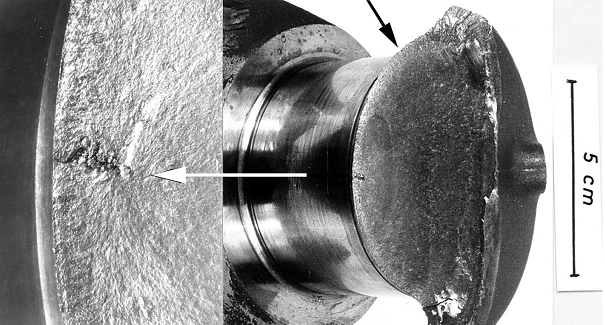
What causes cold shuts and misruns in aluminum die casting?
Cold shuts and misruns happen when molten aluminum does not fully fuse or fully fill the die cavity before solidification. These defects often appear as flow lines, incomplete edges, thin-section discontinuities, or weak seams where two metal fronts meet without proper fusion.
Possible causes include low effective melt temperature, low die temperature, poor venting, unsuitable gate location, long flow paths, thin walls, flow restrictions, or premature solidification. RFQ drawings should call out thin walls, long ribs, deep pockets, sharp transitions, and cosmetic flow-line limits so the die casting process can be reviewed before tooling.
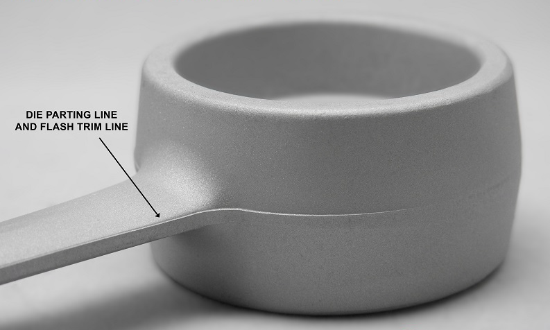
Why do flash and parting-line defects appear?
Flash is excess aluminum that escapes at the die parting line, slide interface, ejector area, or shutoff surface. Flash and parting-line mismatch matter because they can increase trimming cost, interfere with assembly, affect sealing faces, or create burrs near handled or cosmetic surfaces.
Flash can be related to die wear, clamping control, die fit, thermal expansion, metal pressure, contamination on shutoff surfaces, or insufficient maintenance. The drawing should identify allowable burr height, no-burr edges, cosmetic surfaces, and post-trim inspection requirements. If a parting line crosses a sealing or sliding interface, the quotation should include machining or controlled finishing after casting.
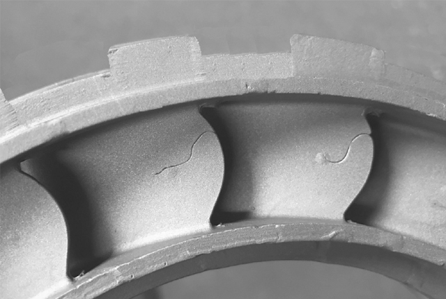
How should hot cracks and tears be reviewed?
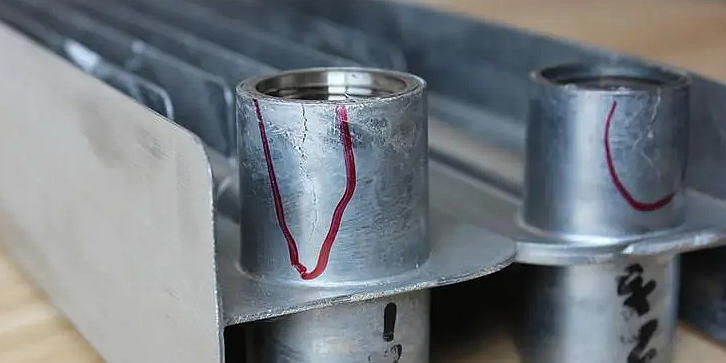
Hot cracks and hot tears are separations that form while the casting is still solidifying and restrained by the die or by uneven cooling. These defects are serious when the crack intersects a load path, pressure boundary, machined surface, or mounting feature.
Hot-crack review should consider alloy behavior, wall-section transitions, fillet radius, rib design, restrained shrinkage, gate location, cooling balance, and ejection stress. The RFQ should identify structural features, pressure zones, and inspection needs. Dye penetrant inspection, visual standards, sectioning, X-ray inspection, or CT inspection may be considered when crack risk affects acceptance criteria.
What inspection evidence helps control aluminum die casting defects?
Inspection evidence should match the defect risk and the part function. Dimensional reports and CMM inspection support tolerance control. Visual inspection standards support cosmetic surfaces, flash, scratches, and gate-removal quality. X-ray or CT inspection supports internal porosity review. Leak testing and pressure testing support sealed housings, pump bodies, valves, and pressure-related parts.
Buyers should define acceptance criteria before quotation. For safety-critical or regulated applications, the drawing package should define qualification requirements, documentation needs, and final validation responsibility. The die casting supplier can support manufacturing and inspection evidence, while final validation remains the buyer's responsibility.
Defect Type | Likely Manufacturing Cause | Part Risk to Review | RFQ or Inspection Evidence |
Gas porosity | Air entrapment, poor venting, turbulent filling, moisture, or dissolved gas | Leakage, reduced pressure tightness, exposed voids after machining, and strength reduction | Leak test, pressure test, X-ray inspection, CT inspection, sectioning, or porosity acceptance criteria |
Shrinkage and microporosity | Uneven wall thickness, thick sections, cooling imbalance, or insufficient local feeding | Weak load paths, pressure-zone defects, corrosion paths, and machined-surface voids | Wall review, cooling review, machining allowance, sectioning, X-ray, CT, or functional test |
Cold shut and misrun | Incomplete filling, long flow paths, poor venting, low effective temperature, or thin wall sections | Weak seams, incomplete edges, cosmetic flow marks, and assembly interference | Flow review, visual standard, dimensional check, thin-wall review, and sample approval |
Flash and parting-line mismatch | Die wear, clamping control, shutoff contamination, thermal expansion, or slide mismatch | Burrs, trimming cost, sealing-surface interference, cosmetic defects, and assembly risk | Burr limit, visual standard, trimming process, machining note, and first article inspection |
Hot cracks and tears | Restrained shrinkage, alloy sensitivity, sharp transitions, uneven cooling, or ejection stress | Crack growth, load-path failure, pressure leakage, and reject risk after machining | DPI, visual standard, sectioning, X-ray inspection, CT inspection, and acceptance criteria |
What RFQ information reduces aluminum die casting defect risk?
A useful aluminum die casting RFQ should include the 2D drawing, 3D model, alloy grade, annual quantity, prototype or production stage, wall thickness, critical dimensions, datum scheme, cosmetic surfaces, pressure or leak requirements, machining allowance, coating or surface treatment, heat treatment if required, and inspection method.
Defect reduction depends on early design and process review. When buyers identify functional surfaces, no-burr areas, sealing faces, threaded holes, bearing seats, and pressure boundaries at the quotation stage, the die casting route can be reviewed with more realistic tooling, machining, finishing, and inspection planning.
Related FAQs