Aluminum Die Cast Prototypes: CNC, Rapid Tooling, or Die Casting?
For many OEM programs, aluminum die cast prototypes are not just optional samples. They are a critical step in deciding whether a part is ready for tooling investment and mass production. Before committing to a hardened die, buyers usually need to verify much more than the external shape. They need to confirm assembly fit, functional dimensions, machining allowance, wall-thickness logic, cosmetic expectations, and whether the geometry is suitable for stable production. That is why prototype strategy is one of the most important early decisions in Aluminum Die Casting development.
The difficulty is that “prototype” can mean very different things. Some projects only need a fast CNC-machined aluminum sample to confirm fit and assembly. Others need low-volume parts made through rapid tooling to evaluate process behavior more realistically. In some cases, buyers need actual die cast prototype parts because only the real process can reveal shrinkage-related behavior, gate influence, flash line location, or post-casting machining conditions. Choosing between CNC, rapid tooling, and die casting depends on what exactly the prototype must prove.
Why Aluminum Die Cast Prototypes Are Needed Before Tooling Investment
Hard tooling for die casting represents a significant investment, so buyers usually want to reduce risk before approving production dies. Prototype parts are used to validate whether the design is mature enough for that step. In practice, a prototype may be needed to check assembly clearances, mounting interface accuracy, wall rigidity, heat dissipation geometry, sealing features, machining datum logic, and target appearance after blasting, coating, or painting.
Prototype work is especially important for parts with thin walls, multiple machining surfaces, cosmetic exterior faces, integrated ribs, or tight packaging inside larger assemblies. Even when the CAD model appears correct, prototype parts often reveal hidden issues such as tolerance stack-up, tool-access constraints, insufficient draft logic, weak rib transitions, or unrealistic finish expectations. This is why a well-planned prototype phase can reduce overall development cost rather than add unnecessary delay.
CNC Prototypes vs Aluminum Die Cast Prototypes
CNC prototypes are often the fastest route when the main goal is to verify external geometry, assembly interface, or mechanical function without immediately reproducing the exact die casting process. Through CNC Machining Prototyping, buyers can obtain aluminum parts quickly and check mounting holes, bearing locations, gasket interfaces, housing fit, and general design proportions. CNC is particularly effective when the design is still evolving and frequent revisions are expected.
However, CNC-machined parts do not fully represent actual die cast conditions. They do not reproduce casting shrinkage behavior, gate-related material flow effects, as-cast skin structure, parting-line logic, or real die-cast surface texture. They may also hide manufacturability problems because a CNC part can often be machined from solid stock even if the same geometry would be difficult, inefficient, or unstable in pressure die casting. That means CNC is excellent for design validation, but less reliable for full process validation.
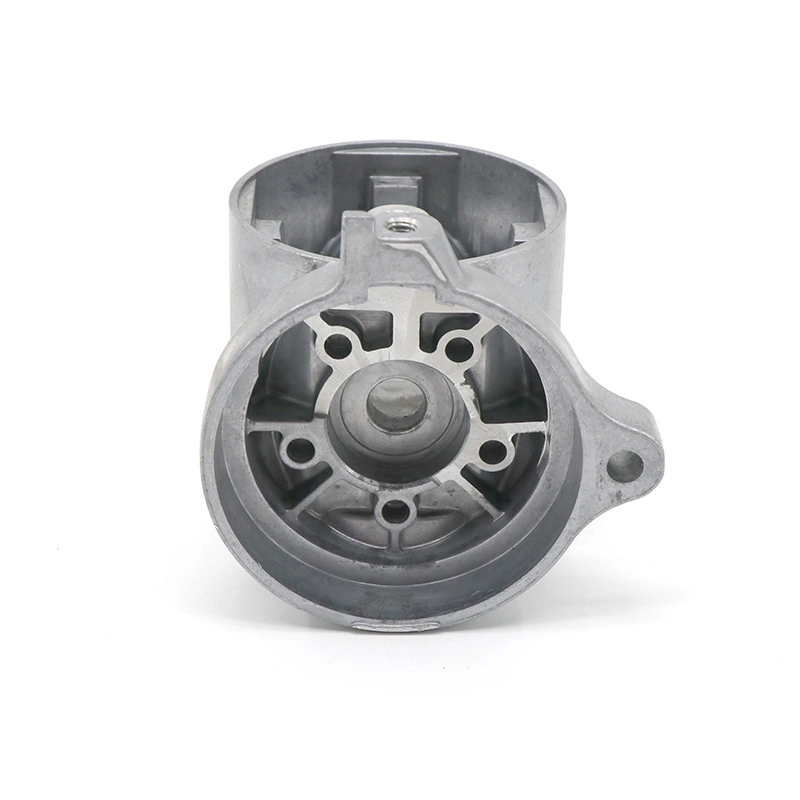
By contrast, aluminum die cast prototype parts are much more useful when the buyer wants to evaluate real casting behavior. These parts can help reveal how thin walls fill, how local shrinkage behaves, whether ejector and parting-line locations are acceptable, how much stock remains for machining, and how surface quality compares with expectations. The trade-off is that true die casting prototypes usually require more preparation than simple CNC parts, especially if dedicated tooling is involved.
CNC vs. Die Cast Prototype Selection Summary
Prototype Route | Best Used For | Main Advantage | Main Limitation |
|---|---|---|---|
Fast geometry and assembly validation | Quick turnaround and easy design revision | Does not fully represent die casting process behavior | |
Aluminum Die Cast Prototype | Real process validation and production-risk review | Closer to actual casting conditions and finish behavior | Higher preparation effort than CNC prototyping |
Low-volume validation before full tooling | Useful bridge between concept sample and mass production | Still not always identical to hardened production tooling |
Rapid Tooling for Low-Volume Validation
Rapid tooling is often the most practical middle ground when buyers need more realistic pre-production validation than CNC can provide, but are not yet ready to invest in full production dies. In this stage, the goal is usually to produce a limited batch of parts that better simulate real manufacturing conditions while controlling development cost. For some projects, this can be the most efficient way to confirm geometry maturity, assembly repeatability, post-machining allowance, and finish feasibility before the production tool is released.
This route is especially valuable when the part is expected to move quickly into serial production, but the team still needs physical validation of fit, handling, and downstream process compatibility. Buyers planning this step should also review broader Prototyping options and the role of Rapid Molding Prototyping in bridging concept development and production launch.
How Prototype Parts Help Verify Assembly, Shrinkage, Machining Allowance, and Finish
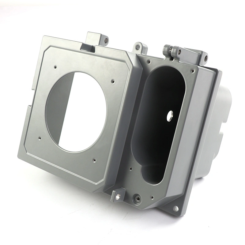
Prototype parts should be selected based on what the project team is trying to verify. If the primary concern is assembly fit, then accurate hole placement, interface faces, gasket seats, and mating geometry are the priority. If the concern is die casting readiness, then wall-thickness transitions, rib structure, parting-line exposure, and likely shrinkage-sensitive zones become more important. If the concern is post-processing, then machining allowance, trim access, cosmetic surfaces, and finishing response must be evaluated.
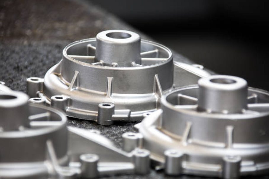
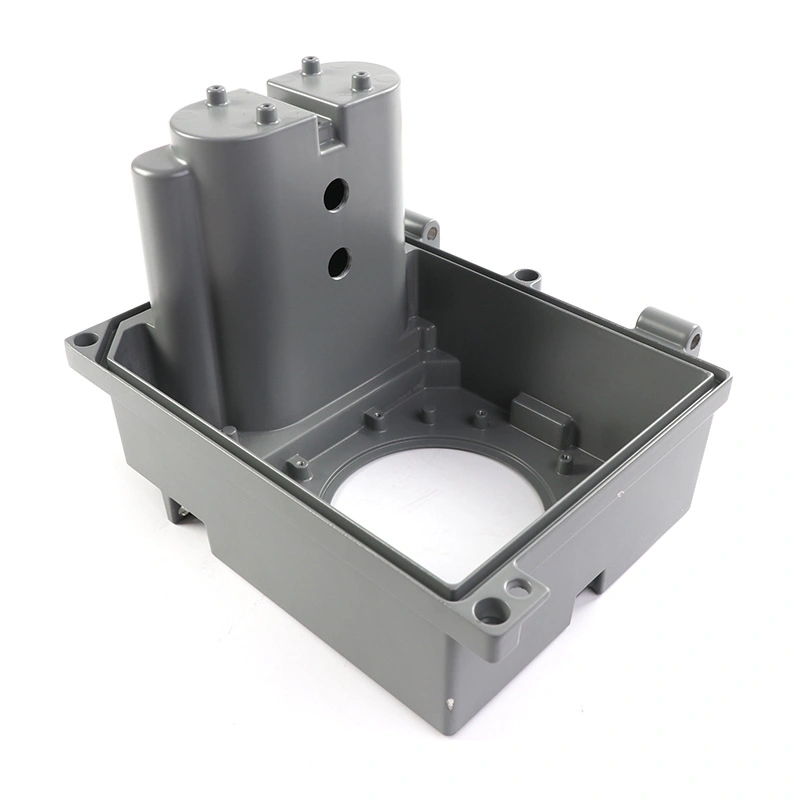
For aluminum housings and structural parts, prototype validation often reveals whether wall thickness is balanced enough for stable casting, whether local bosses or ribs need redesign, whether threads should be machined or redesigned, and whether cosmetic surfaces can tolerate gate and ejector logic. It can also help confirm whether the part should receive bead blasting, polishing, painting, or anodizing-related finishing after casting. Buyers evaluating surface expectations may also find it useful to review anodized aluminum parts and anodizing cast aluminum if the final product has decorative or corrosion-resistance requirements.
What Each Prototype Stage Can Verify
Validation Item | CNC Prototype | Rapid Tooling Prototype | Die Cast Prototype |
|---|---|---|---|
Assembly fit | Strong | Strong | Strong |
Basic functional geometry | Strong | Strong | Strong |
Casting shrinkage behavior | Weak | Moderate | Strong |
Machining allowance review | Moderate | Moderate to strong | Strong |
Surface finish realism | Limited | Moderate | Strong |
Parting-line and ejection logic | Weak | Moderate | Strong |
Batch repeatability review | Weak | Moderate | Strong |
When to Move from Prototype to Die Casting Production
The right time to move into production tooling is usually when the prototype phase has answered the most important technical and commercial questions. That means the assembly fit is confirmed, critical features are stable, wall structure is accepted, machining strategy is defined, and surface-finish expectations are aligned with the real process. It also means the annual quantity and business case are strong enough to justify die investment.
Buyers should avoid moving too early into full tooling if the prototype still shows unresolved fit issues, uncertain machining allowance, or cosmetic concerns. On the other hand, waiting too long after the design is already stable can delay launch unnecessarily. The decision should be based on whether the project still has design uncertainty or only execution planning left.
Signs That a Project Is Ready for Production Tooling
Readiness Signal | Why It Matters |
|---|---|
Assembly fit is verified | Reduces risk of tool correction due to interface errors |
Critical machining features are defined | Allows tooling and machining route to be optimized together |
Wall thickness and rib logic are accepted | Improves casting stability and reduces defect risk |
Surface expectations are realistic | Prevents cosmetic disagreement after tool release |
Annual volume is confirmed | Supports tooling amortization and process selection |
RFQ package is complete | Improves quotation accuracy, tooling design, and launch timing |
Buyer Checklist: 3D Files, 2D Drawings, Material, Finish, Quantity
A good prototype plan starts with a complete RFQ package. Suppliers can only recommend the right prototype route if they understand what the buyer is trying to validate and what the part is expected to become in production. Incomplete data often leads to choosing the wrong prototype method, which can waste time and increase development cost.
Prototype RFQ Checklist for Aluminum Parts
RFQ Item | Why It Is Important |
|---|---|
3D files | Allow review of geometry, wall thickness, ribs, and tooling logic |
2D drawings | Define critical dimensions, datums, and tolerance priorities |
Material | Clarifies whether the prototype must simulate final alloy behavior |
Finish requirement | Determines whether cosmetic or coating validation is needed |
Quantity | Helps select between one-off CNC, low-volume validation, or process trial |
Machining surfaces | Identifies which features need post-processing review |
Application context | Helps determine whether function, fit, or process realism matters most |
The more complete this information is, the easier it becomes to choose between CNC Machining Prototyping, Rapid Molding Prototyping, and actual aluminum die cast prototype development.
Conclusion: Choose the Prototype Route Based on What Must Be Proven
Aluminum die cast prototypes are most useful when they are chosen based on validation purpose rather than habit. CNC prototypes are ideal for fast geometry and assembly checks. Rapid tooling can support low-volume process-oriented validation before hard tooling. Real die cast prototype parts are best when the team must understand casting behavior, shrinkage influence, machining allowance, and production-like surface conditions.
For buyers developing new OEM aluminum parts, the smartest prototype route is the one that answers the most important technical questions before tooling investment. If you are preparing a new project, start by reviewing Aluminum Die Casting, compare the available Prototyping paths, and align your RFQ around the exact function the prototype is expected to validate.