What Material Are Used for Aluminum Die Casting Mold?
What materials are used for aluminum die casting molds?
Aluminum die casting molds are usually made from hot-work tool steels for the die cavity, core, slide, and insert areas that contact molten aluminum. Aluminum die casting mold material selection should match molten aluminum temperature, injection pressure, part geometry, expected production quantity, thermal fatigue risk, and maintenance requirements. The practical RFQ problem is choosing die steel, insert material, heat treatment, surface treatment, and machining allowance before the mold is built.
Common die material families include H13, H11, SKD61, and equivalent hot-work tool steels, subject to tooling review and material availability. Specialized steels, maraging steels, nickel alloys, or cobalt alloys may be considered for selected inserts or severe wear areas, but these materials should not be treated as default choices without a die-design reason.
Why are hot-work tool steels common for aluminum die casting dies?
Hot-work tool steels are used because an aluminum die casting mold must resist thermal cycling, erosion from molten aluminum flow, pressure loading, soldering, heat checking, and repeated ejection stress. The die material must also support machining, EDM, polishing, heat treatment, repair welding, and maintenance during the tool life.
H13-type and H11-type steels are common because these tool steels can combine hot hardness, toughness, thermal-fatigue resistance, and machinability when correctly heat treated. The exact grade, hardness range, and heat-treatment condition should be selected by the tooling engineer based on the part drawing and production assumptions.
Which die components may need different materials?
The main die block, cavity insert, core pin, slide, ejector pin, sprue bushing, shot sleeve contact area, and replaceable insert may not need the same material. A high-wear gate area may need a different insert strategy from a broad cosmetic cavity surface. A small core pin exposed to high heat and difficult ejection may need different material and heat treatment from a large backing plate.
Replaceable inserts can help when a local area faces erosion, soldering, cracking, or dimensional wear. Buyers should identify critical features, thin ribs, deep bosses, threads, sealing areas, and high-cosmetic surfaces so the die designer can decide whether a separate insert or surface treatment is justified.
How do heat treatment and surface treatment affect die performance?
Heat treatment controls hardness, toughness, dimensional stability, and thermal-fatigue behavior. Poor heat treatment can make a die too brittle, too soft, or dimensionally unstable after machining. Stress relief may also be needed during rough machining, heat treatment, EDM, and finish machining to reduce distortion risk.
Surface treatment may be used to reduce soldering, erosion, wear, or heat checking in selected die areas. Nitriding, PVD coating, polishing, and localized surface finishing can be considered when the aluminum alloy, release agent, gate location, and production quantity justify the extra process. The surface treatment plan should be compatible with die repair and maintenance needs.
How should mold material match the aluminum part requirements?
Mold material should be selected from the casting part requirements. A pressure-tight aluminum housing, a cosmetic cover, a heat sink, and a structural bracket may expose the die to different thermal, flow, and finishing demands. The alloy, wall thickness, gate location, parting line, ejection system, and machining allowance all affect die material stress.
Part design also affects die material choice. Thin walls and long flow paths can increase thermal and erosion stress near gates. Heavy sections can increase heat load and cooling demand. Deep ribs, sharp corners, and small core pins can create cracking or wear risk. These areas should be reviewed before finalizing die steel and insert layout.
What machining and inspection steps are used for die components?
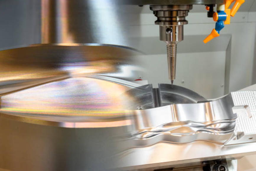
Die components commonly need CNC machining, EDM, wire EDM, drilling, grinding, polishing, heat treatment, stress relief, fitting, spotting, and assembly. Critical areas include cavity surfaces, gate and runner geometry, cooling channels, ejector holes, slide fits, shutoff surfaces, and parting-line surfaces.
Inspection evidence for die components may include dimensional inspection, CMM report, hardness test, heat-treatment record, surface roughness check, fit inspection, and trial-shot review. During sampling, casting defects such as flash, soldering, erosion, heat checking, porosity, cold shut, or shrinkage can indicate whether the die material, insert design, cooling, or process settings need adjustment.
Die Component | Typical Material Family | Manufacturing Risk to Check | RFQ Information Needed |
Main cavity and core inserts | H13, H11, SKD61, or equivalent hot-work tool steel | Heat checking, erosion, soldering, thermal fatigue, and dimensional wear | Aluminum alloy, part quantity, wall sections, cosmetic surfaces, and critical dimensions |
Slides and moving cores | Hot-work tool steel or specialized insert material subject to tooling review | Wear, galling, cracking, ejection stress, and shutoff mismatch | Undercuts, slide travel, core geometry, shutoff surfaces, and lubrication needs |
Gate, runner, and sprue areas | Wear-resistant insert material or treated hot-work steel where justified | Molten metal erosion, soldering, washout, and local heat concentration | Gate location, flow path, fill strategy, expected quantity, and maintenance plan |
Ejector and core pins | Tool steel selected for wear, heat, and pin geometry | Pin bending, wear, sticking, heat cracking, and witness marks on the casting | Boss depth, rib depth, ejection direction, cosmetic limits, and replacement strategy |
Surface-treated areas | Nitrided, coated, or polished die steel when the process review supports it | Coating wear, repair difficulty, soldering, and surface-finish mismatch | Surface finish, release requirements, repair plan, and trial-shot acceptance criteria |
What should buyers provide for an aluminum die casting mold material review?
A useful RFQ should include the 2D drawing, 3D model, aluminum alloy, expected quantity, production stage, critical dimensions, cosmetic surfaces, pressure or leak requirements, machining allowance, parting-line preferences, gate restrictions, ejection limits, surface finish, and inspection requirements.
The mold material decision should be made with the die design, cooling layout, insert strategy, heat treatment, and maintenance plan. Tool steel alone does not solve all die casting problems; the complete die system controls how the aluminum part fills, cools, ejects, and repeats during production.
Related FAQs