What Are The Common Defects in CNC Machining?
CNC Machining Defect Prevention RFQ Decision for Custom Parts: Common CNC machining defects include dimensional deviation, poor surface finish, burrs, tool marks, chatter, workholding deformation, thermal distortion, thread defects, material-related cracking, and inspection mismatches. This article explains why these defects occur in milled, turned, drilled, tapped, and finished custom parts, and what buyers should define in the RFQ to reduce manufacturing risk.
The practical RFQ problem is that defects often come from unclear datum requirements, incomplete drawings, unsuitable material condition, difficult geometry, poor tool access, tight wall sections, uncontrolled burr direction, or missing inspection criteria. Buyers should provide a 2D drawing, 3D model, material grade, critical dimensions, surface finish, threads, heat treatment, coating, inspection method, and acceptance criteria before CNC machining review.

Dimensional Deviation in CNC Machined Parts
Dimensional deviation occurs when a machined feature does not meet the drawing requirement. Common causes include datum misunderstanding, tool wear, workholding distortion, thermal growth, material movement after stress relief, wrong tool offset, fixture variation, or inspection method mismatch. A thin wall, deep pocket, long shaft, or large flat plate may move during or after machining.
Buyers can reduce this risk by clearly defining datums, critical-to-function dimensions, inspection points, and whether the part should be inspected before or after heat treatment, coating, or assembly. If only a 3D model is provided, a 2D drawing is still useful for identifying dimensions that matter most.
Poor Surface Finish, Tool Marks, and Chatter
Poor surface finish may appear as visible tool marks, rough milling passes, tearing, chatter patterns, or inconsistent polishing response. Causes include tool wear, unsuitable cutting parameters, long tool overhang, weak workholding, difficult material, poor chip evacuation, or deep cavity access. Surface finish risk increases when a long tool must reach a deep feature or when thin walls vibrate during cutting.
The RFQ should identify cosmetic surfaces, sealing faces, sliding surfaces, bearing fits, and coating surfaces. A surface roughness requirement should be linked to the part function. Over-specifying every surface can raise cost, while under-specifying functional surfaces can cause fit or wear problems.
Burrs, Sharp Edges, and Thread Defects
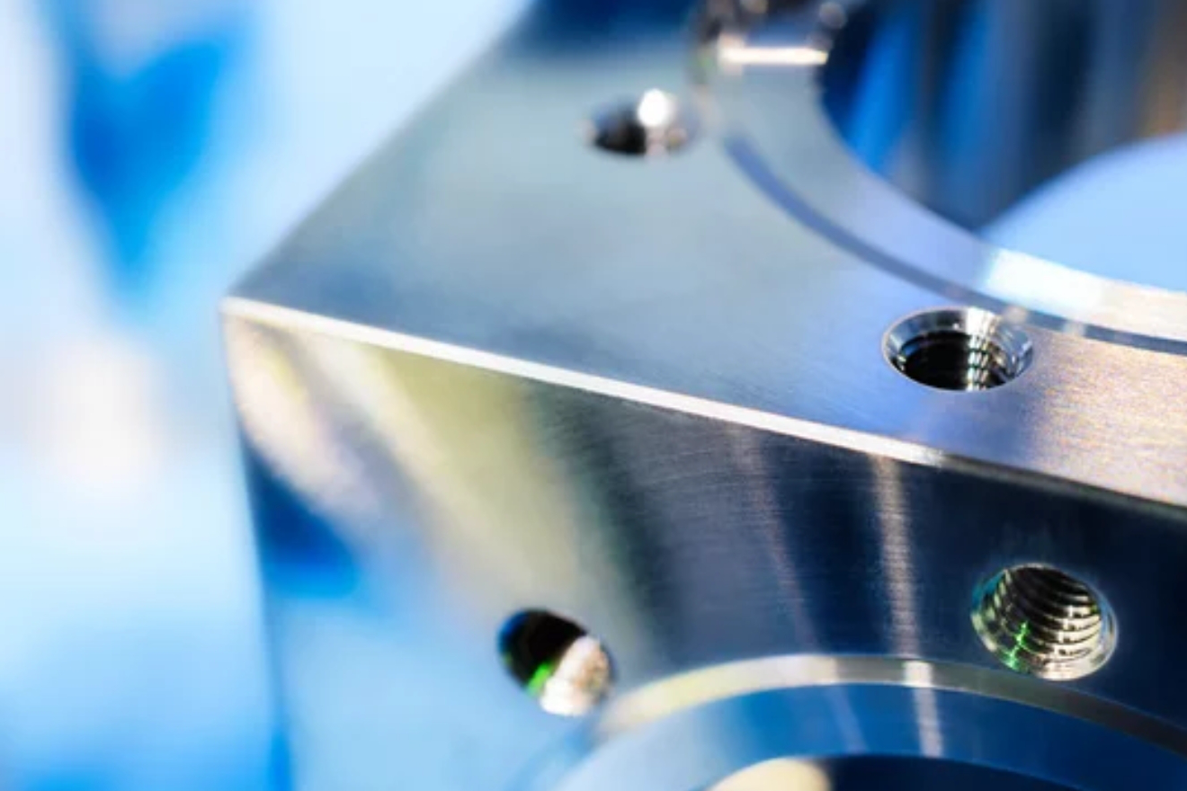
Burrs form where the cutting tool exits the material, especially around drilled holes, milled slots, thin edges, intersecting bores, and threads. Burrs can affect assembly, sealing, electrical contact, sliding fit, or operator handling. Thread defects can come from incorrect tapping conditions, chip packing, poor hole preparation, tool wear, or unsuitable material condition.
Buyers should define edge break requirements, burr-free functional areas, thread standards, thread gauges, blind-hole depth, and whether internal intersections require special deburring. If a burr cannot be reached easily after machining, the design may need a different process sequence or a feature change.
Workholding Marks, Deformation, and Thermal Distortion
Workholding can leave clamp marks or distort thin sections if the part is not supported correctly. Thermal distortion can occur when machining heat, heat treatment, stress relief, coating, or welding changes the part shape. Long parts, thin plates, thin walls, and asymmetric pockets are more sensitive to movement than compact parts.
A good RFQ identifies surfaces that cannot accept clamp marks and features that must remain flat, round, concentric, or parallel. For parts with high internal stress or demanding flatness, buyers should discuss material condition, roughing and finishing sequence, stress relief, and final inspection timing.
Material-Related CNC Machining Defects
Material-related defects include cracking, tearing, built-up edge, poor chip control, hard spots, inclusions, and unexpected tool wear. Aluminum, stainless steel, titanium, copper, brass, engineering plastics, and hardened steels all machine differently. The same toolpath that works for one material may create burrs, heat, or distortion in another material.
Buyers should specify the exact material grade and condition, not only a broad material family. If the material requires heat treatment, hardness testing, passivation, anodizing, plating, or polishing, those steps should be included before quotation because they can change dimensions, surface condition, and inspection requirements.
CNC Machining Defect | Common Cause | Buyer Requirement to Clarify | Inspection Evidence |
|---|---|---|---|
Dimensional deviation | Datum mismatch, tool offset, fixture variation, thermal growth, or material movement. | Critical dimensions, datum scheme, inspection timing, and tolerance priority. | Dimensional report, CMM report, or go/no-go gauge. |
Poor surface finish | Tool wear, chatter, long tool reach, difficult material, or poor chip evacuation. | Functional surface, roughness requirement, cosmetic side, and finishing method. | Surface roughness report and visual standard. |
Burrs and sharp edges | Tool exit direction, intersecting holes, thin edges, or incomplete deburring access. | Burr side, edge break, internal deburring need, and assembly risk. | Visual inspection, burr standard, and fit check. |
Thread defects | Tap wear, chip packing, wrong hole preparation, or material galling. | Thread standard, gauge requirement, blind-hole depth, and insert requirement. | Thread gauge, torque check if specified, and visual inspection. |
Workholding deformation | Clamping force, weak support, thin-wall design, or released residual stress. | No-clamp surfaces, flatness requirement, wall thickness, and stress-relief need. | Flatness check, CMM report, and visual review for clamp marks. |
Preventive Measures Before CNC Machining Production
Defect prevention starts before machining. The drawing should identify datums, functional surfaces, critical dimensions, threads, surface finish, heat treatment, coating, and inspection evidence. The 3D model should match the drawing revision. Material grade and stock condition should be confirmed. If a feature is difficult to machine, the supplier should review tool access, setup count, and fixture strategy before production.
Process controls may include tool-life monitoring, fixture validation, roughing and finishing separation, coolant strategy, chip evacuation, in-process inspection, deburring review, and final inspection. These controls should be selected based on part risk, not applied mechanically to every feature.

What Neway Precision Reviews Before CNC Defect Control
For CNC machining defect control, Neway Precision reviews geometry, material, workholding, tool access, feature sequence, secondary operations, surface finish, and inspection scope. A complete RFQ should include the 2D drawing, 3D model, material grade, quantity, tolerance priorities, surface finish, thread requirements, heat treatment, coating, deburring needs, packaging, and inspection records.
Related FAQs
How Does CNC Machining Ensure Part Consistency And Repeatability?
Which Materials Are Best Suited For CNC Machining In Critical Applications?
What Are Common CNC Machining Methods Used For Precision Parts?
What Types Of Surface Finishes Can Be Achieved With CNC Milling?
Why Is CNC Machining Preferred Over Traditional Machining Methods For Critical Applications?