Metal Parts Prototype Manufacturing: CNC Machining, 3D Printing, Casting, or Rapid Tooling?
When buyers need metal prototype parts, the first challenge is usually not manufacturing. It is process selection. A prototype that is ideal for checking dimensional fit may be a poor choice for validating internal flow channels. A part that is excellent for appearance review may not reflect production economics or tooling feasibility. That is why prototyping for metal parts should begin with one practical question: what exactly does the prototype need to prove?
In real product development, metal prototype manufacturing is used to verify assembly fit, mechanical function, internal geometry, weight, machining allowance, surface finish, manufacturability, and transition-to-production logic. Different prototype routes serve different validation goals. CNC Machining Prototyping is often chosen for dimensional accuracy and fast delivery. 3D Printing Prototyping is often better for complex internal structures and rapid geometry iteration. Casting-based prototypes help evaluate production-like geometry and post-machining logic. Rapid Molding Prototyping can bridge the gap when molded or die-cast parts need low-volume validation before full tooling investment.
Why Metal Prototype Parts Require Process Selection
Many teams assume that any prototype is better than no prototype. In practice, the wrong prototype method can slow the project down by validating the wrong thing. A CNC-machined block may confirm mounting-hole positions but fail to represent thin-wall casting behavior. A 3D printed metal part may reproduce internal channels well but not represent the final machined surface or the exact cost structure of production. A cast sample may better reflect production geometry, but it may not be the fastest route for early design correction.
That is why process selection matters. Buyers should start by identifying whether the prototype is intended to confirm accuracy, function, manufacturability, internal structure, surface quality, or production transition. Once the purpose is clear, the correct process choice becomes easier and the project can move faster with fewer false validation steps. A broader reference for this topic is What Are The Prototyping Methods Of Custom Metal Parts?
CNC Machining for Accurate Metal Prototypes
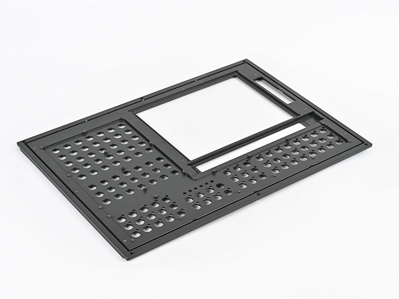
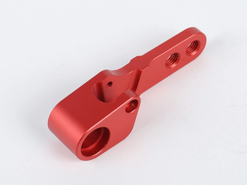
CNC machining is often the default choice when the prototype must be dimensionally accurate, delivered quickly, and made from a real engineering metal. It is especially effective for housings, brackets, fixtures, blocks, covers, flanges, frames, shafts, and other parts where the key validation targets are fit, assembly, flatness, hole location, thread quality, and surface finish after machining. For many engineering teams, CNC Machining Prototyping is the fastest way to confirm whether the CAD model works in the real assembly.
The main advantage of CNC prototypes is control. Critical datums, sealing faces, bearing seats, tapped holes, pockets, and mating surfaces can usually be produced with much higher accuracy than most other prototype methods. This is especially important when the next project decision depends on whether the part fits or functions correctly in a mechanical system. CNC also supports a broad range of metals, which makes it practical when the final material must be represented closely in the prototype stage.
The limitation is that CNC prototypes do not always represent the final production process. A complex internal cavity may be machinable only through expensive setups or EDM, while the final production route might be casting or additive manufacturing. That means CNC is excellent for accuracy and fit, but sometimes weaker for validating production logic.
When CNC Prototyping Is the Best Choice
Validation Need | Why CNC Works Well | Typical Prototype Parts |
|---|---|---|
Assembly fit | High dimensional control and accurate holes, faces, and threads | Brackets, covers, housings, fixtures |
Machined surface evaluation | Represents real post-machined finish and feature quality | Sealing parts, mounting faces, structural frames |
Fast functional testing | Short development cycle without tooling | Mechanical housings, flanges, supports |
Material-specific testing | Can use actual engineering metals | Aluminum, steel, stainless steel prototype parts |
Metal 3D Printing for Complex Internal Structures
Metal 3D printing becomes highly valuable when geometry complexity is the main challenge. Internal channels, lattice structures, topology-optimized forms, weight-reduction features, conformal flow paths, and organic geometries may be difficult or impossible to machine efficiently. In these cases, 3D Printing Prototyping can provide faster design freedom and a more realistic prototype than CNC machining.
This route is especially useful when the prototype must verify internal fluid path design, lightweight architecture, integrated part consolidation, or compact geometries that would otherwise require multiple assembled pieces. It also works well when frequent design revisions are expected, because geometry changes can often be implemented more quickly than in casting or molded prototype routes.
However, buyers should understand that 3D printed prototypes may not always reflect the final production method, cost structure, or as-machined tolerance condition. Support strategy, surface roughness, post-processing need, and build orientation can also affect the result. This means metal 3D printing is strongest when geometry complexity or internal structure is the key question being tested.
When Metal 3D Printing Is the Right Prototype Route
Validation Need | Why 3D Printing Fits | Typical Prototype Parts |
|---|---|---|
Internal channels | Can produce enclosed or highly complex internal geometry | Thermal parts, manifolds, fluid components |
Lightweight structures | Supports lattices and topology-optimized forms | Weight-sensitive housings and structural parts |
Part consolidation | Combines multiple functions into one printed geometry | Integrated brackets, compact mechanical parts |
Fast geometry iteration | Useful when design changes are still frequent | Concept-stage and advanced development prototypes |
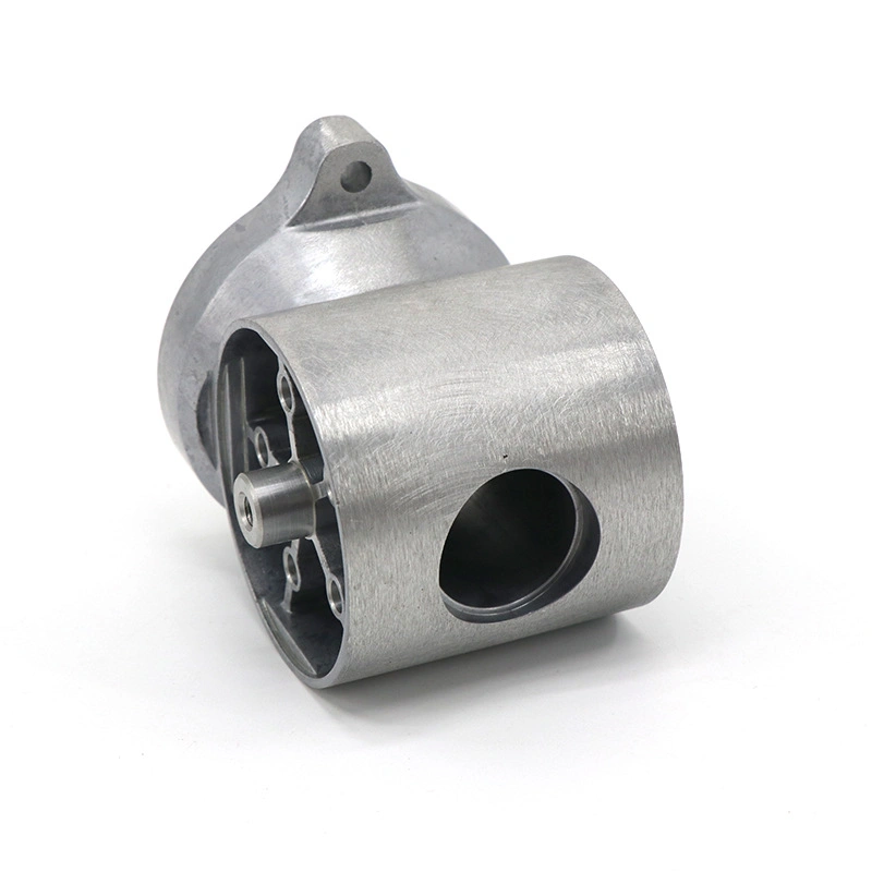
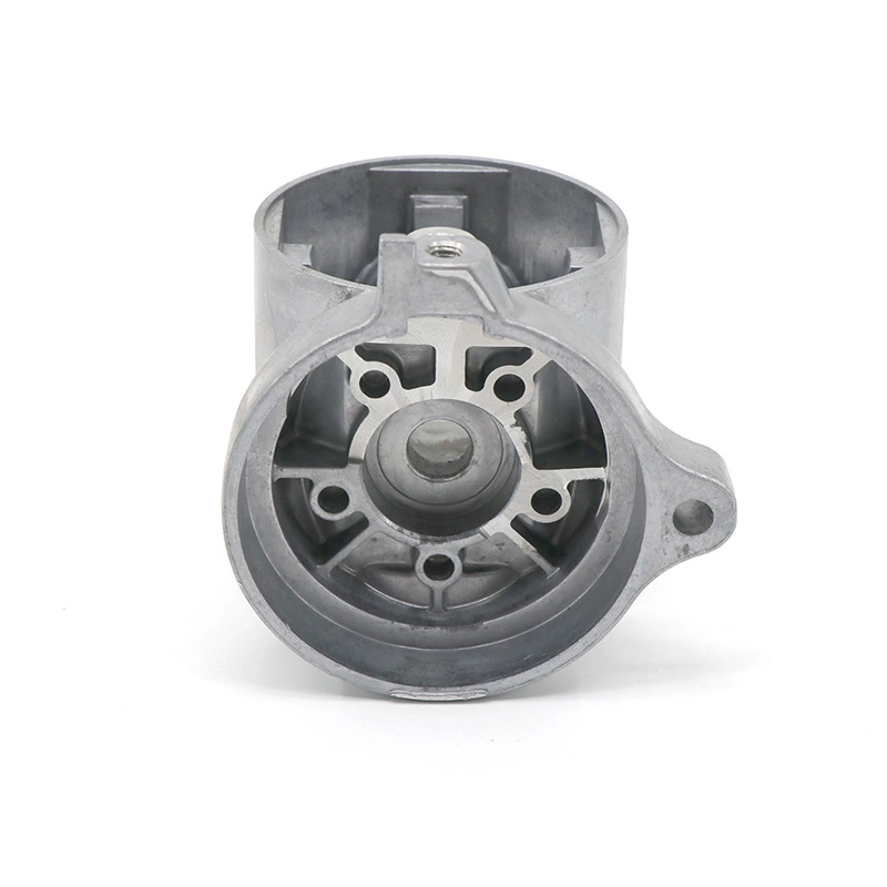
Casting Prototypes for Production-Like Validation
Casting-based prototypes are important when the team needs a part that behaves more like the final production version. In these cases, the purpose is not just to check overall shape. It is to evaluate casting-specific characteristics such as wall behavior, machining stock, draft logic, shrinkage-sensitive areas, and production-like external geometry. This is especially useful for parts expected to move into aluminum die casting, investment casting, sand casting, or similar routes.
A casting prototype can help verify whether ribs are sized correctly, whether sections are balanced enough for stable production, and whether the part has enough allowance for post-machining. It can also reveal where casting geometry differs from a fully machined model and where design modification may be needed before tooling release. For buyers trying to reduce production risk, this kind of validation can be more meaningful than a fast machined sample alone.
The main limitation is that casting prototypes usually require more preparation and may not be as fast as CNC or 3D printing for early concept review. That means they are best used when the design is already relatively stable and the project is moving toward production feasibility evaluation.
Rapid Tooling for Molded or Die-Cast Parts
Rapid tooling is often the best bridge between early prototype work and full production tooling. It is particularly useful when buyers need low-volume parts that reflect tooling-based production logic more realistically than CNC or additive methods can. For projects involving molded or die-cast parts, Rapid Molding Prototyping can help validate assembly, appearance, feature repeatability, and downstream machining strategy before committing to hardened production tools.
This route is valuable when the design is mostly frozen but the team still needs physical evidence before approving serial production investment. It can also help confirm whether the chosen process route is commercially sensible at the intended batch level. Compared with one-off prototypes, rapid tooling often gives better insight into repeatability, handling, and production-like part behavior across a small batch rather than just one piece.
How to Choose by Material, Geometry, Tolerance, and Lead Time
The most effective way to choose a prototype route is to evaluate four factors together: material, geometry, tolerance, and lead time. If the exact production metal and tight machined dimensions matter most, CNC is often the best route. If internal complexity or lightweight geometry is the main challenge, 3D printing may be better. If the team must understand production-like casting behavior, a casting-based prototype is more meaningful. If the goal is low-volume validation before full tooling, rapid tooling becomes more attractive.
Lead time also changes the decision. CNC is often the fastest for accurate machined parts. 3D printing can be faster for complex forms that would otherwise require many setups. Casting or rapid tooling may take longer initially, but they can reduce later risk if the project is moving toward production quickly. The right choice therefore depends on which phase the project is in and what decision the prototype must support next.
Prototype Process Selection by Project Priority
Project Priority | Most Suitable Route | Why |
|---|---|---|
Fast accurate fit check | Best for dimensional accuracy and real machined interfaces | |
Complex internal geometry | Best for channels, lattices, and integrated forms | |
Production-like casting validation | Casting Prototype | Best for shrinkage, machining stock, and casting logic review |
Low-volume pre-production validation | Best bridge before full tooling commitment |
RFQ Checklist for Metal Prototype Parts
A strong RFQ package is one of the most important factors in selecting the correct prototype route. Suppliers can only recommend the right process if they know what the buyer is trying to validate and what the final production goal is. Incomplete RFQs often lead to inaccurate quotations or prototypes that answer the wrong engineering question.
Metal Prototype RFQ Checklist
RFQ Item | Why It Matters |
|---|---|
3D model | Allows evaluation of geometry, internal structures, and manufacturability |
2D drawing | Defines critical dimensions, tolerances, and datum logic |
Material requirement | Clarifies whether prototype must match final metal performance |
Prototype quantity | Helps choose between one-off machining, additive, or low-volume tooling |
Target validation goal | Shows whether fit, function, geometry, or production logic is the main purpose |
Surface finish requirement | Determines whether machining, blasting, polishing, or coating review is needed |
Lead time target | Helps prioritize speed vs process realism |
Expected production process | Helps align prototype route with final manufacturing strategy |
Conclusion: Choose the Prototype Route That Validates the Right Risk
Metal parts prototype manufacturing should not begin with a machine. It should begin with a validation goal. CNC machining is best when dimensional accuracy and fit are most important. Metal 3D printing is stronger for complex internal structures and fast geometry iteration. Casting prototypes are more useful when production-like validation matters. Rapid tooling is ideal when low-volume pre-production evidence is needed before committing to full tooling.
The best prototype route is therefore the one that answers the most important technical and commercial question at the current stage of development. If you are planning a new metal prototype project, start by reviewing Prototyping options and align the RFQ around what the prototype truly needs to prove.