How to select the best thermal interface material between chip and heatsink?
Selecting the best thermal interface material (TIM) between a chip and heatsink is critical for maintaining stable performance and long-term reliability in telecom systems. TIM must minimize thermal resistance, accommodate surface unevenness, withstand environmental stress, and remain stable over thousands of thermal cycles. Neway evaluates each TIM based on operating temperature, pressure, module form factor, and manufacturing method. The selection process is closely aligned with high-precision component manufacturing using ceramic injection molding, aluminum die casting, and CNC machining prototyping to ensure perfect heat transfer from chip to enclosure or spreader.
Assess Thermal Load and Operating Environment
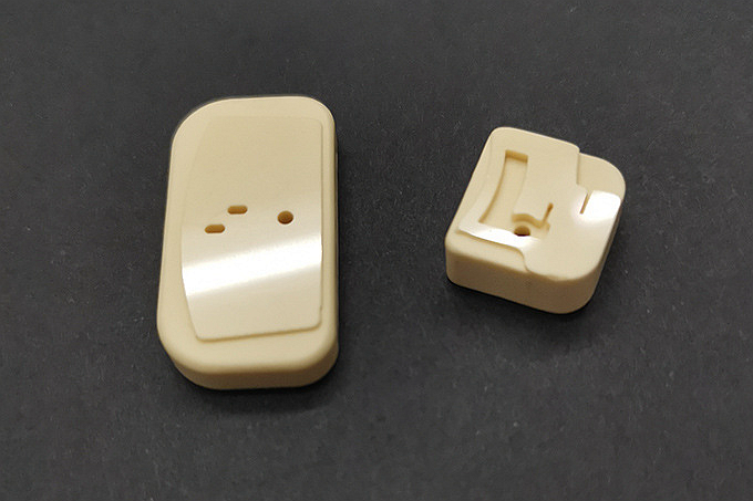
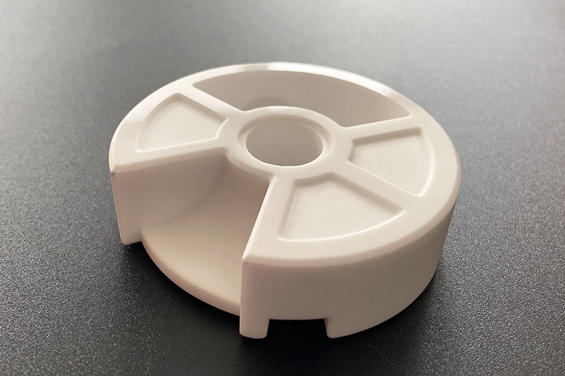
The first step is to determine maximum junction temperature, target temperature drop, and device power density. TIM performance also varies depending on ambient environment. Outdoor telecommunication equipment is exposed to UV radiation, moisture, and vibration, which necessitate TIMs with low thermal resistance and high mechanical stability. In high-temperature zones, ceramic substrates manufactured via alumina CIM or silicon carbide CIM may be used to stabilize heat transfer beneath the TIM layer.
Match the TIM Type to the Application
Common TIM categories include thermal pads, grease, phase-change materials (PCM), and gap fillers. Pads and gap fillers are suited for uneven surfaces and assemblies manufactured through aluminum die casting or sheet metal fabrication. Thermal grease has low resistance but must be applied precisely. For reliability-focused telecom hardware, phase-change TIMs deliver the best balance of performance and stability, particularly when components are bonded to ceramic heat spreaders using CIM components.
Consider Surfaces and Contact Pressure
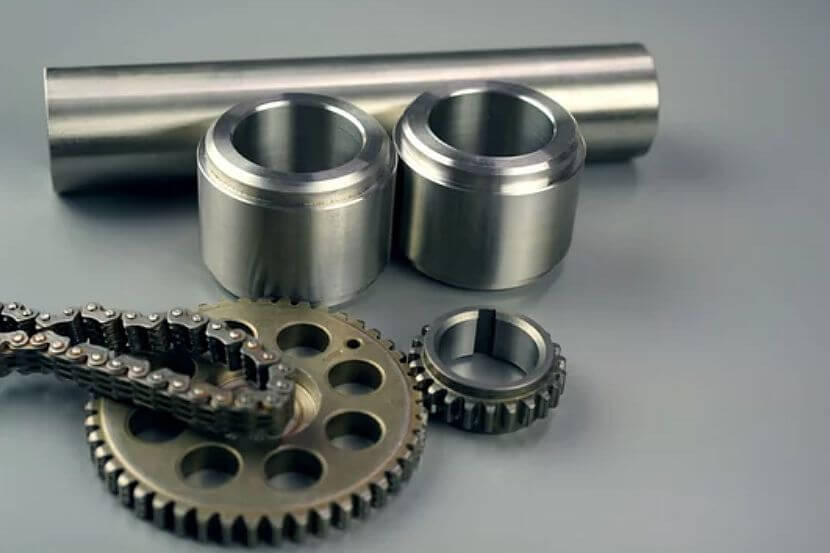
Surfaces must be optimized to ensure efficient thermal contact. CNC machining or precision casting refines the heatsink interface. For air-cooled housings, controlled roughness via tumbling or sandblasting improves bonding but must avoid excessive thickness that hinders TIM flow. Contact pressure must match TIM specifications to prevent dry spots or pump-out during vibration.
Validate with Prototyping and Reliability Testing
The TIM must be tested with realistic surface finishes and loading conditions. Prototype assemblies produced through prototyping are thermally cycled and vibration-tested. TIM degradation is monitored over time, and material shrinkage or migration is evaluated by re-testing thermal resistance. In liquid-cooled designs using copper alloy precision casting, ceramic TIM interface structures formed through CIM can further lower heat resistance and improve dielectric isolation.
Surface Treatments to Improve TIM Performance
Surface finishing can enhance TIM adhesion and improve micro-contact between parts. Methods such as electropolishing or anodizing provide controlled surface properties for consistent TIM distribution. For harsh environments, protective coatings including thermal coating or thermal barrier coating stabilize surface conditions and reduce TIM aging during thermal cycles.


