How to design and control RF cavities to ensure resonance and shielding?
From an engineering perspective, RF cavity design must simultaneously control resonant frequency, Q-factor, and shielding effectiveness while maintaining manufacturability and repeatability. For compact filters, oscillators, and housing-integrated cavities in telecommunication and high-frequency electronics, combining careful EM design with robust metal injection molding (MIM) and surface engineering is the key to achieving stable resonance and reliable shielding over volume production.
RF Cavity Design Objectives
At the design stage, the primary targets are resonant frequency, mode structure, insertion loss, and shielding attenuation. Cavity dimensions must match the calculated EM model while respecting manufacturability constraints such as draft angles, minimum wall thickness, and uniform section transitions. For MIM RF cavities, we typically define critical dimensions (such as resonant chamber length, coupling slots, and tuning features) with tighter tolerances than non-critical features and assign them to dedicated control plans.
Finite element or full-wave EM simulation is used to optimize cavity geometry, coupling apertures, and transition regions. The goal is to concentrate fields where desired, minimize spurious modes, and ensure that current paths lie along smooth, low-resistance surfaces to support a high Q-factor and robust shielding.
Geometry and Tolerance Control with MIM
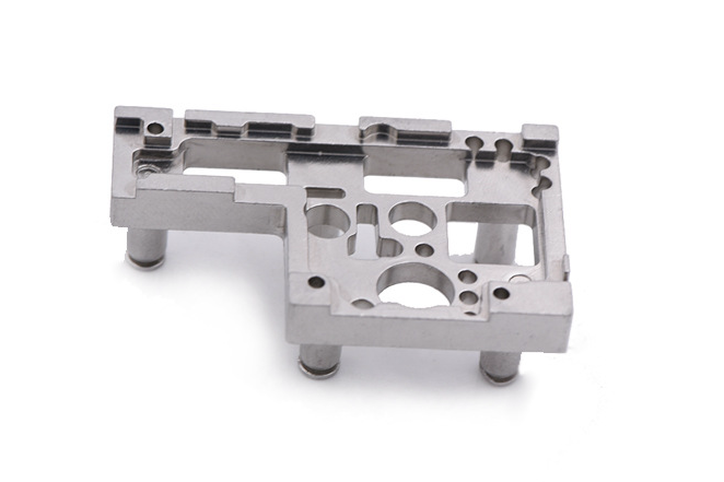
MIM is particularly effective for complex RF cavities that would be very costly to machine. By designing for MIM 17-4 PH or MIM 316L, we can achieve thin walls, intricate internal channels, and integrated mounting features while maintaining good mechanical stability. However, shrinkage during debinding and sintering must be carefully characterized and fed back into the tooling design; we rely on empirical shrink factors and process windows to keep cavity dimensions within the required RF tolerance band.
From a practical standpoint, we avoid abrupt cross-sectional changes, provide adequate radii in corners, and maintain uniform wall thickness wherever possible. These rules minimize distortion risk and help ensure that the final cavity geometry closely aligns with the EM model, which is crucial for maintaining consistent resonant frequency and shielding performance across batches.
Material and Surface Engineering for Resonance and Shielding
Material selection balances mechanical properties, corrosion resistance, and RF performance. For structural housings with integrated cavities, stainless steels such as MIM 316L offer good dimensional stability and corrosion resistance, while soft-magnetic alloys like MIM-Fe-50Ni can be applied where magnetic shielding is important. In practice, high-conductivity plating is typically used on the cavity interior to reduce surface resistance and improve Q.
Surface finish directly affects RF losses. After sintering, internal cavity surfaces are refined by appropriate processes such as polishing or electropolishing to reduce roughness and eliminate sharp asperities that increase skin-effect losses. A subsequent electroplating step (for example, copper or silver plating) provides a high-conductivity surface layer that stabilizes resonance, lowers insertion loss, and enhances long-term shielding performance.
Process Control and Quality Validation
To control resonance and shielding in production, dimensional and process control must be tightly managed. We define critical-to-function dimensions on the cavity and coupling regions, monitor them with CMM or CT scanning, and link them to MIM process parameters (feedstock properties, injection pressure, sintering temperature/time). Statistical process control helps keep the cavity geometry within the RF tolerance window.
On the RF side, validation typically includes vector network analyzer testing of resonant frequency, bandwidth, and insertion loss on representative samples. Shielding effectiveness is verified through standardized test setups that measure attenuation across relevant frequency bands. Where necessary, small tuning features are integrated into the design so that resonance can be fine-tuned after plating without compromising shielding.
Practical Engineering Guidelines
Start with EM simulation to define cavity geometry, then adapt it to MIM design rules before freezing the CAD.
Use stable alloys suitable for metal injection molding and specify surface finishes and plating explicitly in the drawing.
Prototype early using CNC machining prototyping or 3D printing prototyping to correlate EM simulations with measured data.
Define critical cavity dimensions and link them to specific MIM process controls and inspection plans.
Validate shielding and resonance over temperature, humidity, and vibration ranges representative of the end-use environment.


