What steps take RF components from prototype to full-scale production?
Taking RF components from prototype to full-scale production requires aligning electromagnetic design, manufacturing feasibility, metrology, and surface engineering. At Neway, we follow a structured development workflow to ensure that prototype RF behavior is accurately translated into mass-producible parts with repeatable performance. This approach is crucial for hardware deployed in telecommunication, radar, aerospace, and high-speed data systems where reliability and stable RF parameters are mandatory.
Stage 1: Concept and EM Validation
The initial stage focuses on electromagnetic simulations and defining functional geometries. Engineers develop RF models to determine resonant frequency, coupling characteristics, impedance matching, and shielding requirements. Before considering tooling, prototypes are built using CNC machining prototyping or 3D printing prototyping to correlate simulation data with measured VNA performance. Key dimensions, tolerances, and critical features are established based on RF sensitivity.
Stage 2: DFM and Material Selection
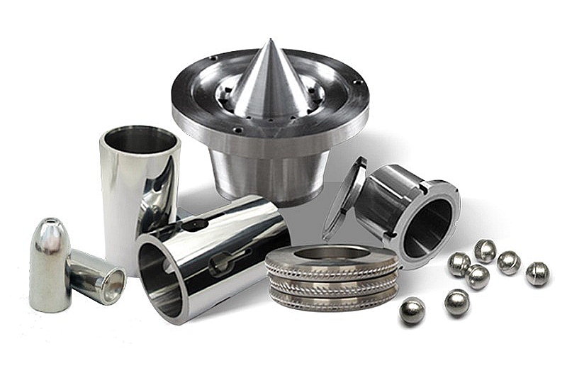
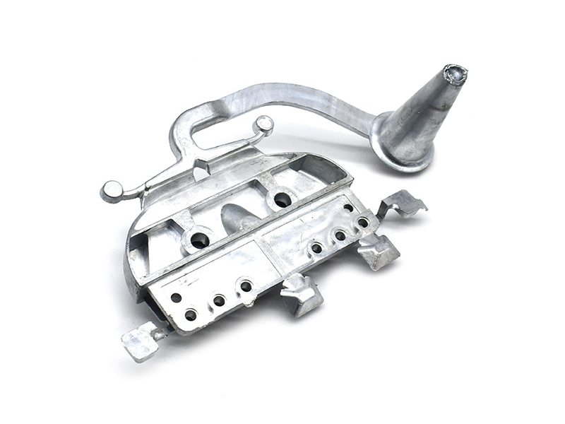
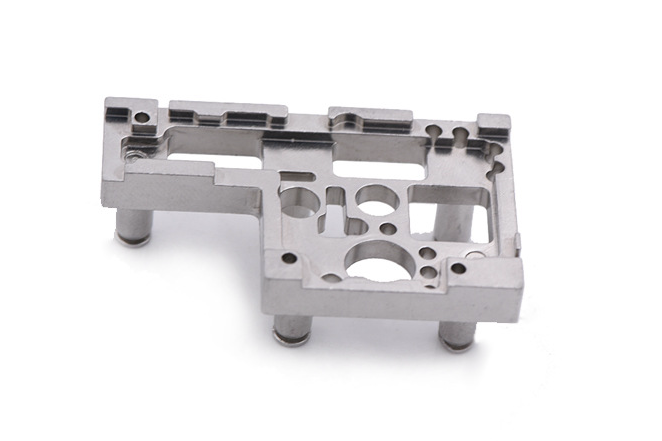
Once proof of concept is validated, models are optimized for manufacturability. Complex RF housings or connector bodies may shift toward metal injection molding using alloys such as MIM 17-4 PH or MIM-304. Lightweight RF structures may use aluminum die casting or precision-cast aluminum. RF-critical surfaces are defined for polishing, electropolishing, or electroplating, and preliminary control plans are drafted to ensure tolerance repeatability.
Stage 3: Tooling and Process Development
Once the manufacturing route is selected, tooling is built for MIM, casting, or injection molding. During this stage, empirical shrink factors and thermal behavior are validated through initial sampling. Tool tuning may require several iterations, especially for internal cavity geometries and waveguide interfaces. Critical RF dimensions are linked to CMM measurements and RF test data to maintain consistency between design intent and physical output.
Stage 4: Pilot Run and Surface Treatment
Before mass production, a pilot run is conducted to verify yield, tolerance reliability, and RF performance. Secondary processes such as polishing, electropolishing, nitriding, or plating are verified for electrical stability and adhesion. For connector housings or enclosure components requiring weight reduction, polymers such as LCP or PEEK may be introduced via plastic injection molding combined with selective metallization.
Stage 5: Production Validation and Ramp-Up
Validated RF components enter ramp-up production. Statistical process control is implemented on RF-sensitive dimensions and surface treatments. Sampling plans involve CMM scans, surface roughness assessment, and VNA testing. In parallel, environmental qualification—thermal cycling, humidity exposure, and vibration—is conducted to ensure performance stability. When consistency is achieved, full-scale manufacturing with continuous monitoring begins.
Engineering Guidelines
Correlate EM simulations with physical prototypes early.
Select manufacturing process based on geometry complexity, cost structure, and RF sensitivity.
Define surface treatment requirements upfront to preserve RF performance.
Monitor dimensions and RF results using integrated metrology and VNA sampling.
Ramp production gradually with SPC to maintain reliability through scale-up.


