اختبار التعب الديناميكي والثابت للتحقق من الهيكل
مقدمة
لا تزال حالات فشل التعب تحديًا حرجًا في المكونات الهيكلية عالية الأداء، خاصة في قطاعات مثل الفضاء الجوي، السيارات، والأجهزة الطبية. يمكن للضغوط الدورية الدقيقة، التي غالبًا ما لا يمكن اكتشافها في الاختبارات الثابتة، أن تؤدي إلى فشل كارثي بعد الاستخدام المتكرر. وهذا يؤكد أهمية كل من اختبار التعب الديناميكي والثابت كأدوات أساسية في تقييم المتانة التنبؤي.
في تصنيع الأجزاء المخصصة، يضمن اختبار التعب أن المواد والأشكال الهندسية تلبي متطلبات التشغيل في العالم الحقيقي. سواء كان التحقق من سلامة صفيحة عظمية من التيتانيوم أو ذراع تحكم من الألومنيوم، يوفر اختبار التعب الهيكلي البيانات الكمية اللازمة للمهندسين لتحسين التصميم، واختيار المواد، وهوامش الأمان. يستكشف هذا المدنى ميكانيكا، ومعدات، وتطبيقات، وفوائد اختبار التعب، مع التركيز على كيفية دعمه للتحقق الهيكلي القوي.
أساسيات اختبار التعب
فهم سلوك تعب المواد
يشير تعب المواد إلى الضرر الهيكلي التدريجي والمحلي الذي يحدث عندما تتعرض المادة لحمل دوري. على عكس الفشل الثابت، الذي يحدث مرة واحدة تحت الحمل الأقصى، ينشأ فشل التعب بمرور الوقت بسبب تكرار الإجهاد، غالبًا دون قوة الخضوع للمادة. على سبيل المثال، يتضمن التعب عالي الدورات عادة سعات إجهاد أقل من 50٪ من قوة الشد القصوى، مع حدوث حالات فشل بعد 10⁶ دورة أو أكثر.
يعتمد سلوك التعب على خشونة السطح، والعيوب الداخلية، وتركيز الإجهاد، والميزات المجهرية. يجب على المهندسين تقييم هذه المتغيرات عند اختيار المواد والأشكال الهندسية للأجزاء للتطبيقات الحرجة. يعد فهم منحنى S-N (الإجهاد مقابل عدد الدورات) أساسيًا لتقدير عمر التعب.
التفريق بين التعب الثابت والديناميكي
يقيس اختبار التعب الثابت كيف تتشوه المواد أو تفشل تحت حمل ثابت ومستمر. وهو مفيد للمواد الهشة أو المكونات المعرضة لإجهاد ميكانيكي طويل الأمد بدون حركة، مثل التركيبات الحاملة للأحمال في المجمعات الهيكلية.
في المقابل، يتضمن اختبار التعب الديناميكي تعريض المكون لحمل دوري يحاكي بيئات التشغيل في العالم الحقيقي. يمكن أن يكون عالي التردد (مثل اختبار الاهتزاز عند 100 هرتز أو أكثر) أو منخفض التردد لمحاكاة الأحمال البطيئة والمتكررة. يستخدم المهندسون الاختبار الديناميكي للكشف عن انتشار الشقوق المبكر، وتدهور الصلابة، وآليات الضرر تحت الحرج الأخرى.
دور أجهزة اختبار التعب في التحقق الهيكلي
أجهزة اختبار التعب الحديثة هي أنظمة متكاملة قادرة على تطبيق أحمال دقيقة، ومراقبة التشوه في الوقت الفعلي، وتسجيل بيانات الفشل عبر ملايين الدورات. وهي تدعم بروتوكولات التحقق في النماذج الأولية المتقدمة، مما يسمح للمهندسين بمحاكاة الاستخدام طويل الأمد بسرعة. وهذا يضمن التحقق من السلامة الهيكلية لمكونات مثل الأقواس، والغرسات الطبية، والأعمدة الدوارة قبل الإنتاج على نطاق واسع.
معدات ومنهجية الاختبار
تكوين جهاز اختبار التعب
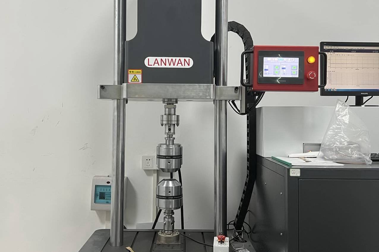
تم تصميم أجهزة اختبار التعب الحديثة لتطبيق الحمل الدقيق تحت ظروف بيئية وتشغيلية مضبوطة. تتكون هذه الآلات عادة من:
هياكل حمل هيدروليكية مؤازرة أو كهروميكانيكية
خلايا حمل (فئة دقة 0.5 حسب ISO 7500-1)
محولات إزاحة (LVDTs أو مقياس التمدد)
حجرات بيئية (لمحاكاة درجة الحرارة والرطوبة)
مولدات موجات يتحكم فيها البرنامج
تستوعب التكوينات القياسية نطاقات قوة من 100 نيوتن إلى أكثر من 100 كيلو نيوتن وترددات من 0.1 هرتز (شبه ثابت) إلى 100 هرتز (اختبار عالي التردد). يمكن أن تكون ملفات الحمل الديناميكي جيبية، أو مثلثة، أو مبرمجة مخصصة بناءً على ظروف عمر الخدمة. تم تصميم التركيبات لمحاكاة قيود الحدود بدقة، مما يضمن توزيعات إجهاد تمثيلية.
تدمج الأنظمة المتقدمة تحكمًا مؤازرًا ذا حلقة مغلقة، مما يسمح بالتحكم الدقيق في القوة أو الإزاحة خلال ملايين الدورات. تتيح الوحدية لهذه الأنظمة استخدامها عبر مختلف الصناعات، من الغرسات الطبية إلى مثبتات الفضاء الجوي.
جمع البيانات والمراقبة
تسجل أنظمة اكتساب البيانات مؤشرات الأداء الحرجة مثل:
الحمل مقابل عدد الدورات (منحنيات F-N)
سعة الإزاحة أو الانفعال
بداية الشق ومعدل النمو
حلقات التخلف لتحليل تبديد الطاقة
تدهور الصلابة الدورية
عادة ما تتم المراقبة في الوقت الفعلي، حيث تلتقط أجهزة الاستشعار عالية الدقة تغييرات صغيرة تصل إلى 0.1 ميكرومتر. يمكن للمهندسين تحديد شروط التوقف، مثل انخفاض الصلابة بنسبة 5٪ أو تجاوز طول الشق لقيمة حرجة، لضمان معايير فشل متسقة.
تتميز معظم أجهزة الاختبار بتوليد تقارير تلقائي، وتخزين الموجات الرقمية، والتكامل مع أنظمة الجودة المؤسسية للتتبع. تدعم هذه الميزات التحسين المستمر للجودة والتحقق من التصميم في البيئات التي يكون فيها الكشف المبكر عن فشل التعب أمرًا بالغ الأهمية.
سيناريوهات التطبيق عبر الصناعات
الأجزاء الهيكلية للفضاء الجوي
تتعرض الهياكل الفضائية الجوية لتقلبات الأحمال الديناميكية الهوائية خلال دورات الطيران، مما يجعل التنبؤ بعمر التعب متطلبًا بالغ الأهمية للسلامة. يجب التحقق من مكونات مثل إطارات جسم الطائرة، ودعامات الأجنحة، ومثبتات التيتانيوم ضد ملايين دورات التحميل تحت ظروف تمثيلية. تحاكي أجهزة اختبار التعب دورات الضغط، والإجهادات الناجمة عن الاضطراب، وتأثيرات الهبوط.
في هذا السياق، يتم محاذاة اختبار التعب مع معايير ASTM E466 و ISO 1099. يتحقق المهندسون من هوامش التصميم عن طريق إجراء اختبارات تعب عالية الدورات تحت حمل محوري، أو انحناء، أو مركب. تعتمد دورات تطوير الفضاء الجوي الحديثة على اختبار التعب المتسارع للهياكل الأولية للكشف عن الشقوق في المراحل المبكرة وتقييم التكرار الهيكلي.
يضمن استخدام بروتوكولات التحقق للفضاء الجوي لهذه المكونات اكتشاف فشل التعب ومنعه من خلال تحسين التصميم واختيار المواد.
مكونات تعليق السيارات
تتعرض أنظمة تعليق المركبات، مثل أذرع التحكم، وقضبان الربط، وحوامل النوابض، لتغير مستمر في الحمل بسبب عدم انتظام سطح الطريق. تحاكي أجهزة اختبار التعب هذه الظروف من خلال تحميل متعدد المحاور أو محاكاة بيانات حمل الطريق. يتضمن الاختبار النموذجي 10⁵–10⁷ دورة عند سعات تصل إلى 60٪ من إجهاد الخضوع.
غالبًا ما يدمج اختبار التعب الديناميكي في قطاع السيارات دورات درجة الحرارة، أو بيئات رذاذ الملح، أو التعب التآكلي لمحاكاة التدهور الفعلي للخدمة. يقيم المهندسون نقطة بداية الشق، واتجاه الانتشار، وحد التعب لتحديد العمر المتوقع للجزء تحت ملفات تحميل المركبات المختلفة.
يستخدم هذا النهج على نطاق واسع في صناعة السيارات، خاصة في مراحل تأهيل المكونات الهيكلية والتحقق من التصميم.
التحقق من الغرسات الطبية
يجب أن تتحمل الغرسات العظمية—مثل سيقان الفخذ، وأكواب الورك، وصفائح تثبيت العمود الفقري—ملايين دورات التحميل داخل جسم الإنسان. تحدد ISO 7206-4، و ISO 14879-1، و ASTM F1717 بروتوكولات التعب الثابتة والديناميكية لمثل هذه الغرسات. تحاكي هذه الاختبارات الأحمال الضاغطة، أو الالتوائية، أو الانحناءية الناتجة أثناء المشي، أو الجري، أو الرفع.
تحافظ أجهزة اختبار التعب ذات حجرات سوائل الجسم المحاكاة على درجة الحرارة الفسيولوجية ودرجة الحموضة أثناء الاختبار. يقيم مهندسو الأجهزة الطبية نمو الشق، واستقرار الواجهة، واهتراء السطح تحت ظروف سريرية ذات صلة.
يطلب قطاع الأجهزة الطبية احتمالات فشل منخفضة للغاية، ويعد اختبار التعب جزءًا لا يتجزأ من تحليل المخاطر، والتحقق من التصميم، وعمليات الموافقة التنظيمية.
تكامل الاختبار الهيكلي مع النماذج الأولية
في عصر تطوير المنتجات التكراري، يسرع دمج اختبار التعب في النماذج الأولية المبكرة من التحقق ويقلل من خطر حالات الفشل في المراحل المتأخرة. يمكن تعريض النماذج الأولية الهيكلية، سواء كانت مخرطة، أو مصبوبة، أو مصنعة بالإضافة، لاختبار التعب الثابت والديناميكي لمحاكاة ظروف الإجهاد للاستخدام الحقيقي.
على سبيل المثال، يمكن أن يخضع نموذج أولي من الألومنيوم مصنوع بالتحكم الرقمي لمفصل ذراع روبوتي لـ 10⁶ دورة حمل دورية عند عزم دوران ±20 نيوتن متر للتحقق من افتراضات التصميم. تكشف نتائج اختبار التعب عن المناطق الضعيفة، وتركيزات الإجهاد، أو المشكلات المتعلقة بإنهاء السطح التي قد لا تظهر في الاختبار الثابت الأساسي. يمكن إجراء تعديلات على الشكل الهندسي، أو صلادة المادة، أو تقنيات المعالجة قبل استثمار الأدوات النهائية.
يقضي المصنعون على التخمين من خلال تضمين الاختبار الهيكلي في سير عمل النماذج الأولية وتعزيز الرابط بين المحاكاة والأداء المادي. في بعض القطاعات، أصبح اختبار تعب النماذج الأولية الآن خطوة رسمية في تقديم المنتجات الجديدة (NPI)، حيث يعمل كبوابة تصميم حرجة قبل التجارب السريرية أو الميدانية.
عادة ما تكون أجهزة اختبار التعب المستخدمة أثناء إنشاء النماذج الأولية وحدية وقابلة للبرمجة، مما يسمح بمحاكاة سيناريوهات تحميل متنوعة. يستفيد المهندسون من دورات التغذية الراجعة السريعة، مما يتيح اختبار تكرارات تصميم متعددة ضمن مرحلة مشروع واحدة. تحسن حلقة التغذية الراجعة الضيقة هذه بشكل كبير وقت الوصول إلى السوق وتتحقق من الموثوقية الوظيفية قبل وقت طويل من بدء الإنتاج بالجملة.
تأثيرات إنهاء السurface والمعالجة الحرارية
يرتبط أداء التعب ارتباطًا وثيقًا بسلامة السطح وظروف الإجهاد المتبقي، والتي تتأثر بعمليات ما بعد المعالجة. يمكن أن تعمل المخالفات السطحية، والشقوق المجهرية، وأكاسيد القشور كمواقع بداية لشقوق التعب، مما يقلل بشكل كبير من عمر المكون تحت الإجهاد الدوري.
يمكن لإنهاء مصقول أو معالج بالرصاص على مكونات عالية الإجهاد، مثل ريش التوربينات أو الغرسات العظمية، أن يحسن مقاومة التعب بأكثر من 20٪. في المقابل، يمكن للأسطح غير المصقولة أو كما هي بعد الصب أن تقلل من قوة التعب بسبب زيادة الخشونة (Ra > 3.2 ميكرومتر) وعدم اتساق البنية المجهرية.
تعمل علاجات ما بعد التشغيل الآلي مثل التلميع أو الأكسدة على تحسين الجماليات والأداء الوظيفي تحت حمل التعب. تحسن عمليات المعالجة الحرارية—مثل التبريد والتقسية—البنية الحبيبية الداخلية وملفات الإجهاد المتبقي لزيادة حدود التحمل. على سبيل المثال، قد تصل قوة التعب للفولاذ 4140 المعياري إلى 400 ميجا باسكال، ولكن بعد المعالجة الحرارية، يمكن أن ترتفع هذه القيمة إلى 600 ميجا باسكال.
يكون التفاعل بين إنهاء السطح وسلوك التعب حرجًا بشكل خاص في المكونات المعرضة لأحمال انحناء أو التواء ديناميكية. يمكن أن تزيد العلاجات السطحية والحرارية المحسنة من عمر التعب عن طريق تقليل نقاط البداية وتأخير انتشار الشقوق.
معايير الاختبار والمعايير الصناعية
لضمان موثوقية وقابلية مقارنة نتائج اختبار التعب، يجب على المصنعين الالتزام بالمعايير المعترف بها دوليًا. الأكثر شيوعًا هي ASTM E466 لاختبارات التعب المحوري و ISO 1099 لاختبارات الانحناء الدوار. تحدد هذه المعايير الشكل الهندسي للعينة، وبروتوكولات التحميل، ومعايير الفشل، مما يضمن قابلية التكرار عبر مرافق الاختبار.
بالنسبة للمكونات الهيكلية في قطاع الفضاء الجوي، يجب أن يمتثل التحقق لمعايير الفضاء الجوي الأكثر صرامة، مثل MIL-STD-1530 و FAA AC 25.571. غالبًا ما تفرض هذه اللوائح اختبار تعب موسع عبر ملفات الحمل الديناميكية والثابتة تحت ظروف درجة حرارة ورطوبة مرتفعة. على سبيل المثال، عادة ما يتم اختبار تعب مكونات الألومنيوم 7075-T6 المستخدمة في إطارات الطائرات لتتجاوز 10⁷ دورة عند سعات إجهاد تبلغ 150–200 ميجا باسكال.
من ناحية أخرى، تلتزم مكونات مجموعة نقل الحركة للسيارات عادة بـ DIN 50100 و SAE J1099، مما يضمن المتانة تحت إجهادات الالتواء، والحرارية، ومتعددة المحاور. غالبًا ما تتضمن الاختبارات دورات محورية-التوائية مركبة للأجزاء الثقيلة لمحاكاة التحميل في الميدان.
يجب أن يتماشى التحقق من التعب الهيكلي ليس فقط مع المعايير الصناعية، ولكن أيضًا مع سيناريوهات استخدام العملاء المحددة. يجب أن يأخذ تخطيط الاختبار في الاعتبار العوامل الواقعية مثل تعقيد طيف الحمل، والتعرض للتآكل، وتكرار الخدمة لضمان أداء الأجزاء بشكل موثوق طوال عمرها التصميمي.
دراسة حالة: التحقق من مكون الصب بالقوالب تحت الحمل العالي
الخلفية والأهداف
تطلب مورد إلكتروني من الدرجة الأولى التحقق الهيكلي لقوس دعم مصبوب من الزنك-الألومنيوم يستخدم في علب الاتصالات الخارجية. كان من المتوقع أن يتحمل الجزء أحمال رياح متقلبة، واهتزاز من تشغيل المعدات، وإجهاد دوري من تقلبات درجة الحرارة. العمر الافتراضي المتوقع: 15 عامًا أو 10⁷ دورة تحميل. تضمنت مخاطر الفشل الرئيسية بداية شق التعب عند الحواف الحادة والتدهور بسبب مسامية السطح.
إعداد الاختبار والطريقة
تم تعريض مكون الاختبار، المنتج عبر صب الزنك بالقوالب، لحمل ديناميكي جيبي بتردد 25 هرتز وحمل ذروة 3.2 كيلو نيوتن. كرر ملف الاختبار الأحمال الناجمة عن هبات الرياح اليومية حسب IEC 60068-2-6. تم تنفيذ 1.2 مليون دورة لكل عينة، مع اختبار خمس عينات للفشل أو البقاء.
خضعت العينات لفحص سطح قبل الاختبار، وفحوصات أبعاد، وتحليل كسر بعد الاختبار. تضمن اكتساب البيانات:
تتبع الصلابة في الوقت الفعلي
تقدم طول الشق عبر الارتباط الصوري الرقمي (DIC)
مراقبة انخفاض تردد الرنين
النتائج والإجراءات الهندسية
نجت ثلاث عينات من دورات الاختبار الكاملة مع انخفاض في الصلابة أقل من 2٪. فشلت عينتان عن طريق بداية شق التعب عند نصف قطر ضلع حاد، وتمت إثارته إلى مسامية محلية وزاوية سحب غير كافية. نفذ الفريق تعديلات تصميم طفيفة، بما في ذلك زيادة أنصاف أقطار الأضلاع ومراجعة وضع البوابة أثناء الصب، مما قلل من تكوين الفراغات المحلية.
أكد الاختبار المتابع الامتثال الكامل لأهداف متانة التعب. قام برنامج اختبار التعب بالتحقق من التصميم الهيكلي وقاد تحسين العملية المنبع في تصميم الأدوات ومعلمات الصب.
الخاتمة
يعد اختبار التعب الديناميكي والثابت ركيزتين أساسيتين في التحقق الهيكلي للمكونات الدقيقة. من إطارات الفضاء الجوي إلى تعليق السيارات والغرسات الطبية، يحدد سلوك التعب الأداء طويل الأمد والسلامة. بينما يسلط التعب الثابت الضوء على تشوه المواد المعتمد على الوقت تحت حمل ثابت، يكشف التعب الديناميكي عن نقاط الضعف التي تنشأ تحت إجهاد تشغيلي متكرر.
يسمح دمج اختبار التعب مبكرًا في عملية تصنيع الأجزاء المخصصة للمهندسين بتحسين الشكل الهندسي، والمواد، ومسارات المعالجة بثقة قائمة على البيانات. سواء في النماذج الأولية أو الإنتاج على نطاق واسع، يدعم اختبار التعب تحليل الفشل التنبؤي وتحسين التصميم التكراري. علاوة على ذلك، تتغذى نتائج الاختبار في نماذج العناصر المحدودة، مما يعزز دقة المحاكاة للتصاميم من الجيل التالي.
أجهزة اختبار التعب هي أكثر من أدوات تشخيصية—فهي عوامل تمكين لموثوقية المنتج، والامتثال التنظيمي، والميزة التنافسية. مع استمرار ارتفاع متطلبات الأداء الهيكلي، سيزداد دور التحقق المتقدم من التعب في ضمان التميز الوظيفي عبر الصناعات المتنوعة.
